
Image forming apparatus and method for producing drive unit

a technology of drive unit and image, applied in the direction of electrographic process apparatus, instruments, optics, etc., can solve the problems of image defects and abnormal noise, and achieve the effect of suppressing image defects

Pending Publication Date: 2022-10-27
CANON KK
View PDF3 Cites 0 Cited by
  • Summary
  • Abstract
  • Description
  • Claims
  • Application Information

AI Technical Summary

Benefits of technology

The present invention is about an image forming apparatus that can prevent image defects and abnormal noise caused by attaching foreign substances to the drive gear. This is achieved by overlapping the drive unit and disposing the electrical board in a way that reduces the likelihood of such attachment.

Problems solved by technology

Therefore, it is possible that image defects such a periodic band shaped density unevenness (called banding and the like) occur.
Further, when a foreign substance attached to the drive gear is bitten by the drive gear, an occurrence of an abnormal noise is caused.

Method used


Image

  • Image forming apparatus and method for producing drive unit
  • Image forming apparatus and method for producing drive unit
  • Image forming apparatus and method for producing drive unit

Examples


Embodiment Construction

Image Forming Apparatus

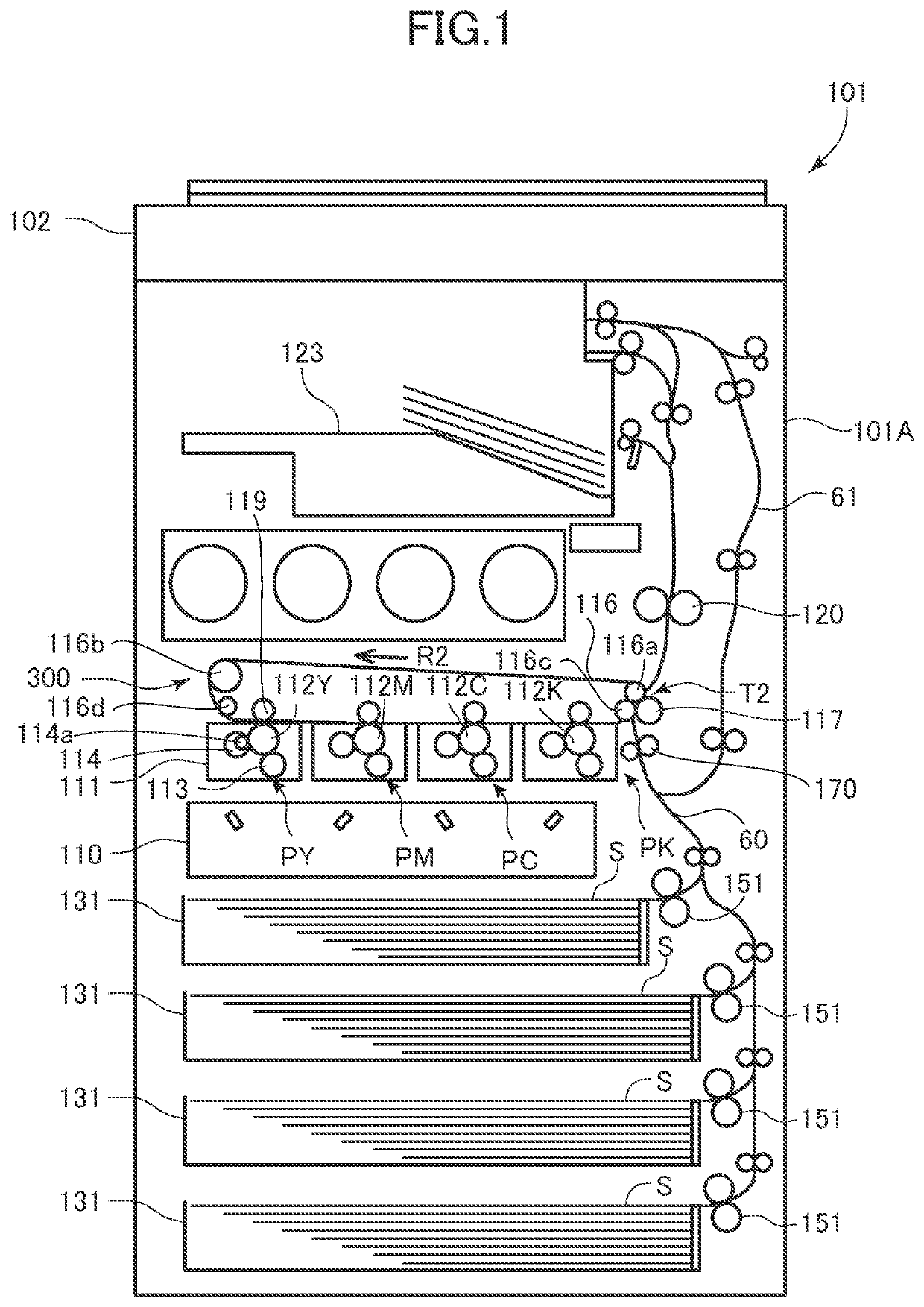
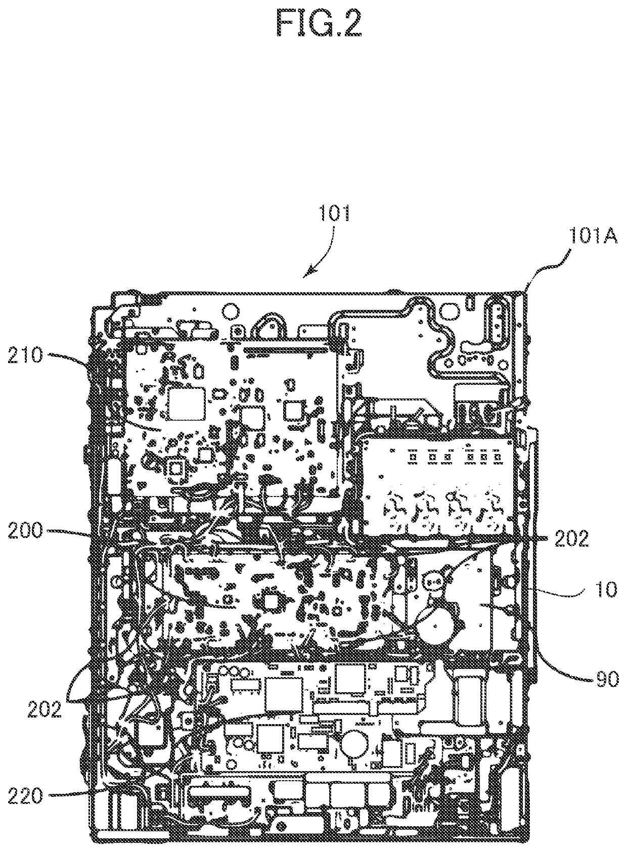
[0017]An image forming apparatus of this embodiment will be described using FIGS. 1 and 2. The image forming apparatus 101 shown in FIG. 1 is a full color printer of an intermediate transfer system. The image forming apparatus 101 includes image forming units PY, PM, PC, and PK respectively forming toner images of yellow, magenta, cyan, and black. The image forming apparatus 101 forms the toner image on a recording material S in accordance with an image signal from a document reading apparatus 102 disposed on an upper side in the vertical direction or an external apparatus, not shown, such as personal computer. The recording material S includes a sheet material such as paper, a plastic film, cloth, and the like. To be noted, herein, a side on which a user stands at the time of operating an operation panel, not shown, so as to operate the image forming apparatus 101 is referred to as “front”, and the opposite side is referred to as “back”.

[0018]In the image for...


PUM


Abstract

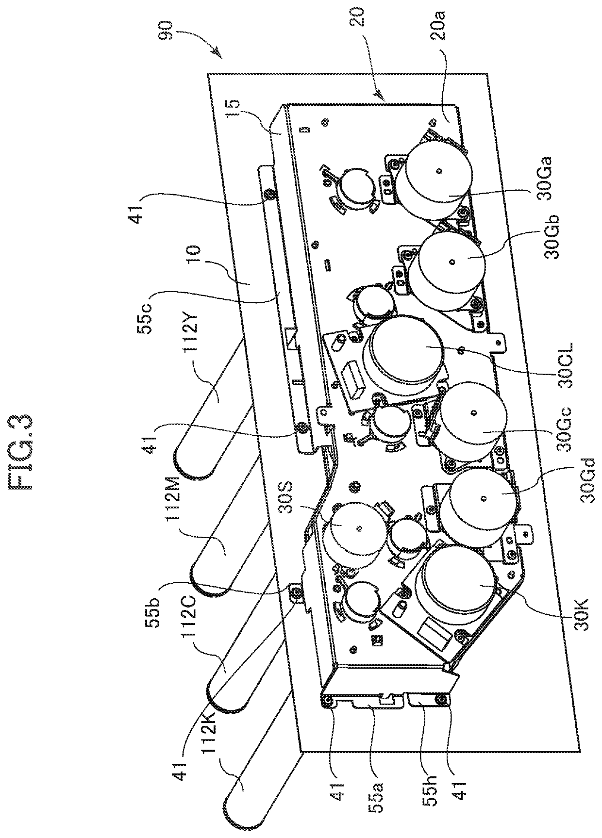
An image forming apparatus includes a support frame, a driving device including a first supporting portion configured to hold the drive source on a first surface and configured to rotatably support the drive gear on a second surface, and a second supporting portion configured to support the drive gear with the first supporting portion, a board holding member disposed in a manner overlapping the first supporting portion in a rotational axis direction of the drive gear, and a third supporting portion disposed between the first supporting portion and the board holding member in the rotational axis direction, and configured to support the board holding member, one end of the third supporting portion being fixed to a side of the first surface of the first supporting portion by a first fastening member, another end of the third supporting portion being fixed to the board holding member by a second fastening member.

Description

BACKGROUND OF THE INVENTIONField of the Invention[0001]This disclosure relates to an image forming apparatus, such as a printer, a copier, a facsimile, and a multifunction machine, which uses an electrophotographic technique.Description of the Related Art[0002]A drive roller or the like so as to rotatably drive, for example, a photosensitive drum, developing sleeve, and intermediate transfer belt, serving as a rotary member, is disposed in an apparatus body of an image forming apparatus such as a printer, a copier, a facsimile, and a multifunction machine integrally combining those functions mentioned above. Further, so as to drive such a rotary member, a driving device integrating a motor and drive gear is mounted on a back side plate of the image forming apparatus. Further, so as to miniaturize the image forming apparatus, for example, an electrical board such as a power supply control board for supplying power and a main control board for performing various control processes rela...

Claims


Application Information

Patent Timeline
IPC IPC(8): G03G21/16
CPCG03G21/1671G03G21/1619G03G21/1647G03G21/168G03G2221/1657G03G15/80
Inventor TANABE, YUICHIKUROSU, YUKI
Owner CANON KK
Learn More