
Computer implemented method and system for navigation and display of 3D image data

a computer and image data technology, applied in computing, instruments, electric digital data processing, etc., can solve the problems that conventional 2d displays cannot render a flat representation, 2d images such as 2d ultrasound images cannot represent three-dimensional structures typical of humans, and the technology of 2d displays has not been primarily developed for the specific requirements of clinical settings

Pending Publication Date: 2022-10-27
GUYS & ST THOMAS NHS FOUND TRUST +1
View PDF4 Cites 0 Cited by
  • Summary
  • Abstract
  • Description
  • Claims
  • Application Information

AI Technical Summary

Benefits of technology

Embodiments of this patent are a method and system for creating 3D images that can be peeled away to focus on specific structures. The system uses an intuitive user interface to define the structure of interest and a masking kernel that can be adjusted by the user to control how much surrounding structure is shown. The system also allows the user to change perspective and view the highlighted structure from different angles. The main technical effect of the invention is that it provides a more powerful and flexible tool for analyzing and visualizing 3D image data, while reducing the specialist knowledge and skills required to operate the imaging system.

Problems solved by technology

2D images such as 2D ultrasound images cannot represent three-dimensional structures typical of human or animal body organs because they can only capture one 2D slice of a cross-section.
A current limitation of 3D imaging is that although the data is 3D in its nature, conventional 2D displays can only render a flat representation (projection, slice, casting, etc) of the image on a screen.
Such technologies have, however, not been primarily developed for the specific requirements of a clinical setting.
3D systems tend to be expensive and their interfaces alien to users used to working in 2D.
A further issue with three dimensional rendering of data is that the volume of information portrayed to the user increases substantially.
While this can be argued to be positive, it also makes navigation and changing of views in the three dimensional space and assimilating information on a feature of interest more difficult.
Often these issues mean that the user drops back to working on two-dimensional slices of the 3D image data using a 2D display and user interface.
While this may be preferred by users, it loses information from the three-dimensional view that may be of relevance or interest to the user (for example from a different orientation).
As a result, many of the advantages of the 3D system are lost and the 3D system ends up becoming an expensive 2D system.

Method used


Image

  • Computer implemented method and system for navigation and display of 3D image data
  • Computer implemented method and system for navigation and display of 3D image data
  • Computer implemented method and system for navigation and display of 3D image data

Examples


Embodiment Construction

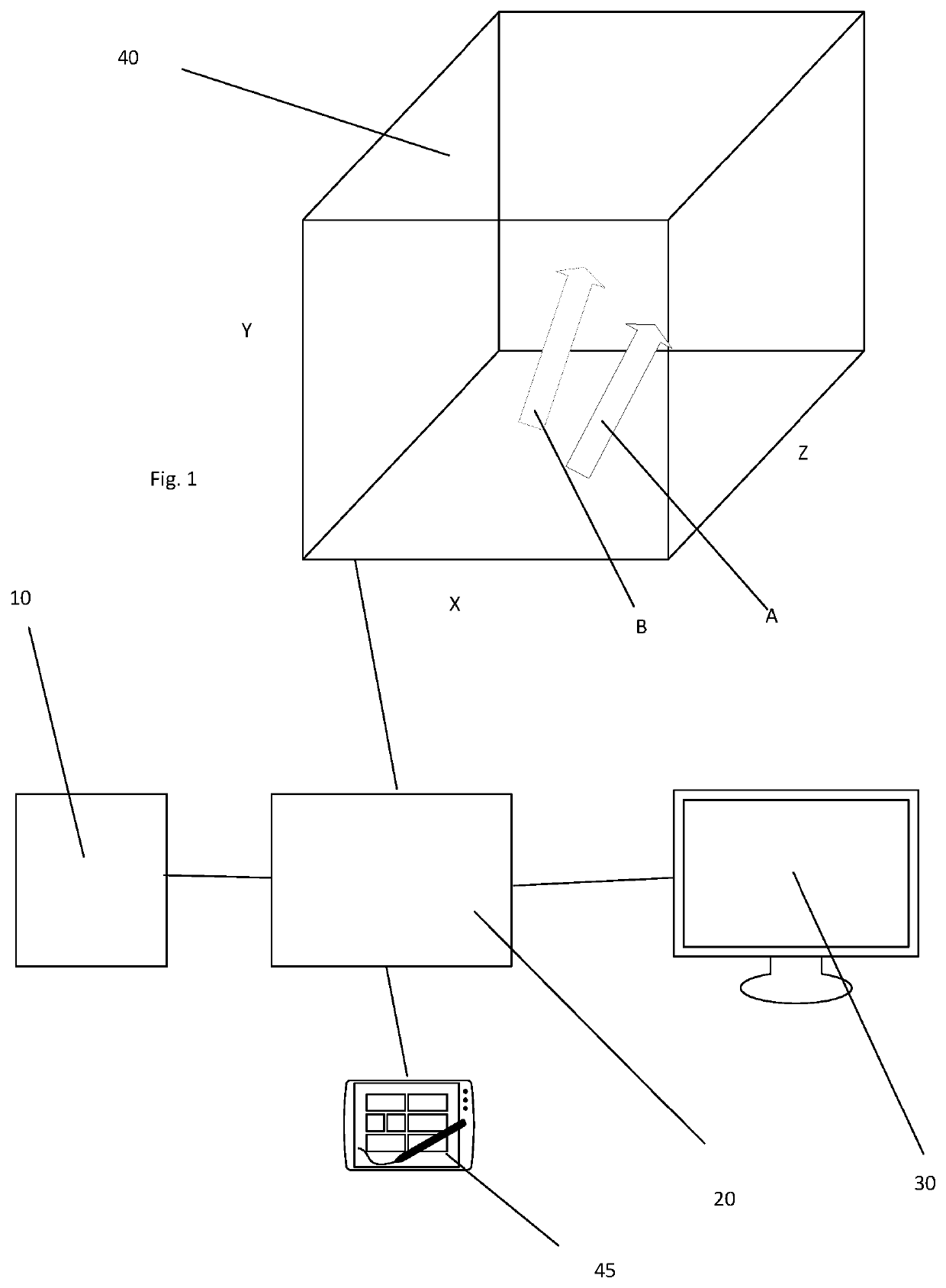
[0051]Embodiments of the present invention are directed to method and systems for displaying and applying user inputs to manipulate 3D imagery.

[0052]There exist many sources of 3D image data including 3D imaging scanners. Embodiments may receive data directly from a 3D image data source or may receive data that has been previously acquired and stored in a data repository or similar.

[0053]3D image data is typically encoded in the form of a 3D array of voxels. In 3D imaging, the term “voxel” is used to refer to a scalar or vector value on a regular grid in three-dimensional space. As with pixels in a bitmap, voxels themselves do not typically have their position (their spatial coordinates) explicitly encoded along with their values. Instead, rendering systems infer the position of a voxel based upon its position relative to other voxels (i.e., its position in the data structure that makes up a single volumetric image).

[0054]In embodiments of the present invention, the 3D image data is...


PUM


Abstract

A computer-implemented method and system for navigation and display of 3D image data is described. In the method, a 3D image dataset to be displayed is retrieved and a highlight position is identified within the 3D image dataset. A scalar opacity map is calculated for the 3D image dataset, the opacity map having a value for each of a plurality of positions in the 3D image dataset, the respective value being dependent on the respective position relative to the highlight position, and on the value of the 3D image at the respective position relative to the value of the 3D image at the highlight position. The opacity is applied to the 3D image dataset to generate a modified 3D image view.

Description

FIELD OF THE INVENTION[0001]The present invention relates to a system and computer implemented method for navigation and display of three-dimensional imaging and is particularly applicable to three-dimensional imaging of the human anatomy for the purpose of medical diagnosis and treatment planning.BACKGROUND TO THE INVENTION[0002]Conventional imaging scanners are used for various purposes including imaging human and animal bodies for diagnosis and guidance during medical intervention such as surgery. Other uses for imaging scanners include structural analysis of buildings, pipes and the like.[0003]A conventional medical ultrasound scanner creates two-dimensional B-mode images of tissue in which the brightness of a pixel is based on the intensity of the echo return. Other types of imaging scanners can capture blood flow, motion of tissue over time, the location of blood, the presence of specific molecules, the stiffness of tissue, or the anatomy of a three-dimensional (3D) region.[00...

Claims


Application Information

Patent Timeline
IPC IPC(8): G06T19/00G06T19/20G06F3/04815G06F3/04845
CPCG06T19/003G06T19/20G06F3/04815G06F3/04845G06T2219/2024G06T2210/41G06T2210/62G06T2200/24G06T2219/2012
Inventor MUNRO SIMPSON, JOHNPUSHPARAJAH, KUBERANGÓMEZ HERRERO, ALBERTOSCHNABEL, JULIA ANNEWHEELER, GAVINDENG, SHUJIETOUSSAINT, NICOLAS
Owner GUYS & ST THOMAS NHS FOUND TRUST
Learn More