
Stator for electric motor

a technology for electric motors and stator coils, which is applied in the direction of dynamo-electric machines, electrical apparatus, magnetic circuit shapes/forms/construction, etc., can solve the problems of preventing the operation efficiency of electric motors from being lowered, and the stator coil lifespan is reduced

Pending Publication Date: 2022-10-27
LG MAGNA E POWERTRAIN CO LTD
View PDF0 Cites 0 Cited by
  • Summary
  • Abstract
  • Description
  • Claims
  • Application Information

AI Technical Summary

Benefits of technology

The present invention relates to a stator for an electric motor that can prevent the lifespan of its coil from being shortened due to partial discharge of hairpins. Additionally, it can suppress interference and partial discharge of hairpins, even without using a separate member, when the hairpins are coupled to a stator core.

Problems solved by technology

This may result in suppressing reduction of lifespan of the stator coil due to the partial discharge of the hairpins.
This may result in preventing operation efficiency of the electric motor from being lowered due to the generation of the circulating current of the plurality of phase-parallel coils.

Method used


Image

  • Stator for electric motor
  • Stator for electric motor
  • Stator for electric motor

Examples


Embodiment Construction

[0152]Hereinafter, implementations of the present disclosure will be described in detail with reference to the accompanying drawings. For the sake of brief description with reference to the drawings, the same or equivalent components will be provided with the same reference numbers, and description thereof will not be repeated. A singular representation used herein may include a plural representation unless it represents a definitely different meaning from the context. In describing the present invention, if a detailed explanation for a related known technology or construction is considered to unnecessarily divert the gist of the present disclosure, such explanation has been omitted but would be understood by those skilled in the art. The accompanying drawings are used to help easily understand the technical idea of the present disclosure and it should be understood that the idea of the present disclosure is not limited by the accompanying drawings.

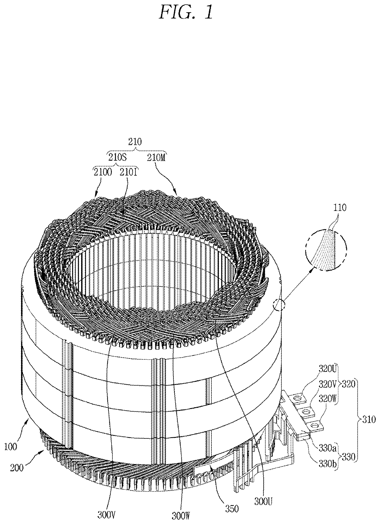
[0153]FIG. 1 is a perspective view...


PUM


Abstract

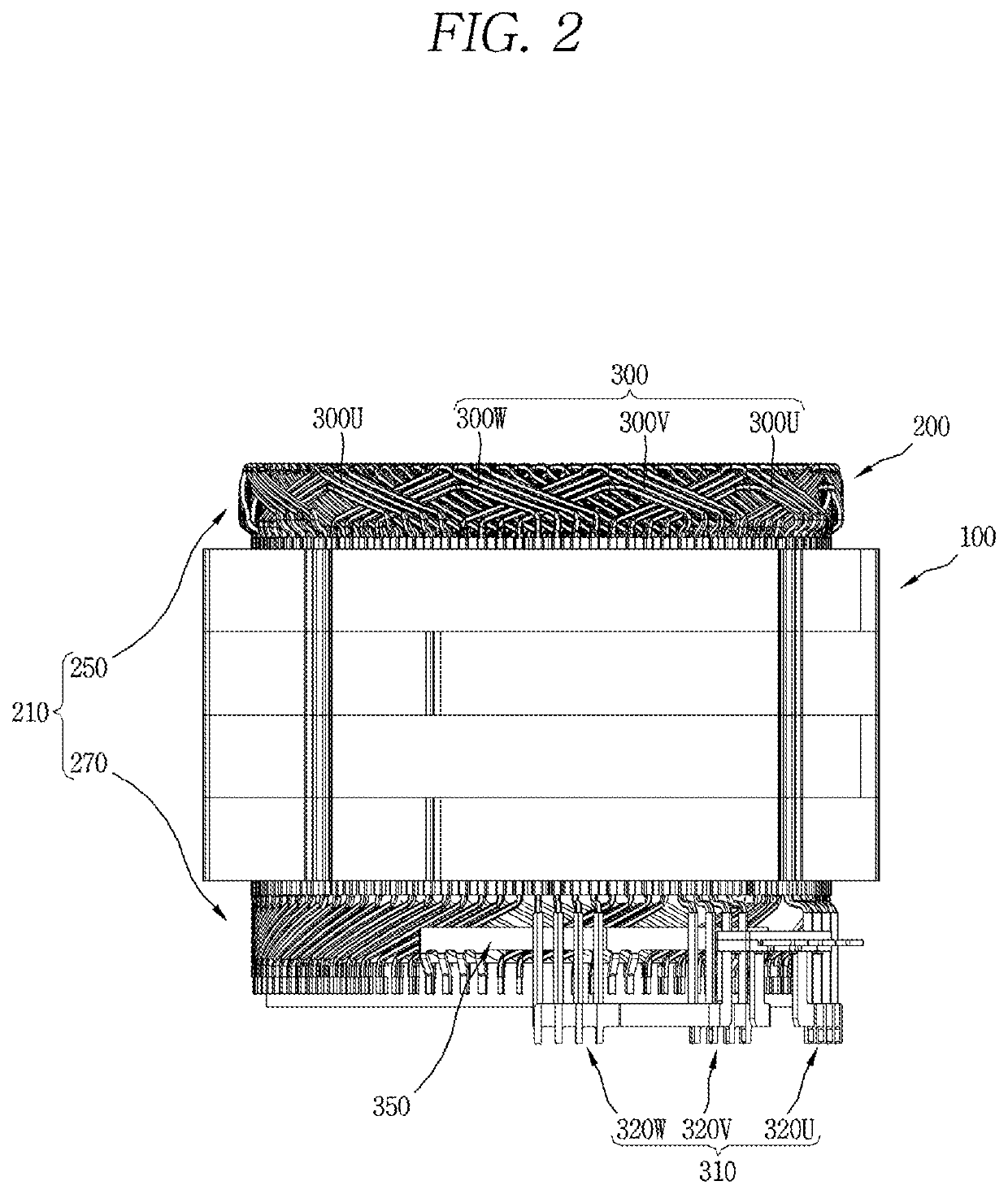
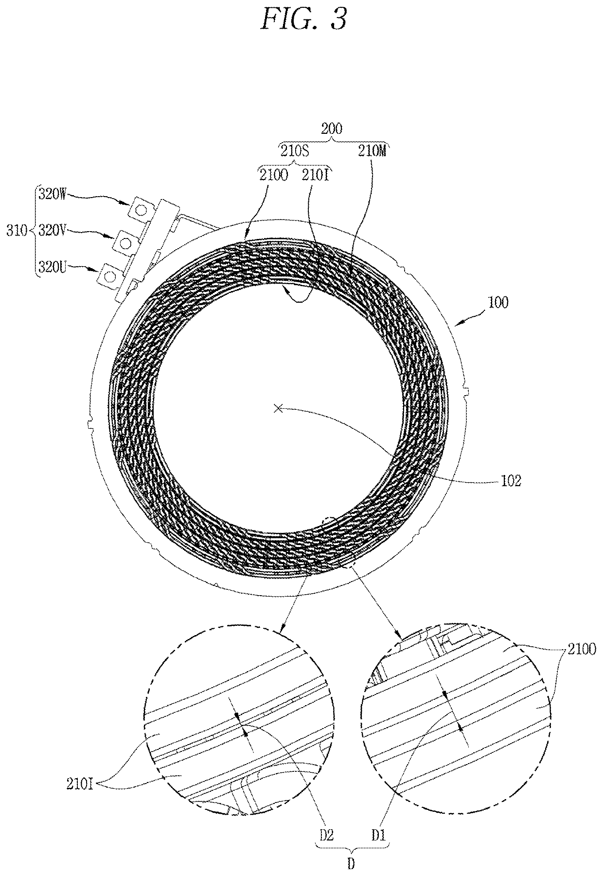
A stator for an electric motor according to the present disclosure includes a stator core having a plurality of slots and teeth, and a stator coil wound via the plurality of slots, wherein the stator coil includes a plurality of hairpins inserted into the plurality of slots and connected in series with one another, wherein the plurality of hairpins is spaced apart from one another by a partial discharge suppression distance to suppress partial discharge between adjacent hairpins, wherein a partial discharge suppression distance between hairpins with a high voltage distribution ratio is farther than a partial discharge suppression distance between hairpins with a low voltage distribution ratio when power is applied to the stator coil. This may result in suppressing reduction of lifespan of the stator coil due to the partial discharge of the hairpins.

Description

TECHNICAL FIELD[0001]The present disclosure relates to a stator for an electric motor.BACKGROUND[0002]As is well known, an electric motor is a device that converts electrical energy into mechanical energy.[0003]Such electric motor typically includes a stator and a rotor disposed to be rotatable relative to the stator.[0004]The stator includes a stator core having a plurality of slots, and a stator coil wound around the stator core via the plurality of slots.[0005]The stator coil is configured as a conductor having a circular cross-section or a rectangular cross-section.[0006]The conductor having the circular cross-section has a relatively small cross-sectional area and is wound with a relatively large number of turns.[0007]The conductor having the rectangular cross-section (hereinafter, referred to as “hairpin”) has a relatively large cross-sectional area and is manufactured in an approximately “U” shape.[0008]The hairpin includes insertion parts inserted into different slots, a cro...

Claims


Application Information

Patent Timeline
IPC IPC(8): H02K3/12H02K1/16
CPCH02K3/12H02K1/16H02K3/28H02K2213/03H02K15/0421
Inventor PARK, GYEONGJAESHIN, HOJUNSUNG, WONJUNGSEOL, HYUNSOOLEE, JEONGMINKIM, KYEONGHWANKIM, JAEMIN
Owner LG MAGNA E POWERTRAIN CO LTD
Learn More