
Vehicle slip regulation method and apparatus, electronic device and medium

Pending Publication Date: 2022-11-03
TIANJIN SOTEREA AUTOMOTIVE TECH LMITED CO +1
View PDF20 Cites 0 Cited by
  • Summary
  • Abstract
  • Description
  • Claims
  • Application Information

AI Technical Summary

Benefits of technology

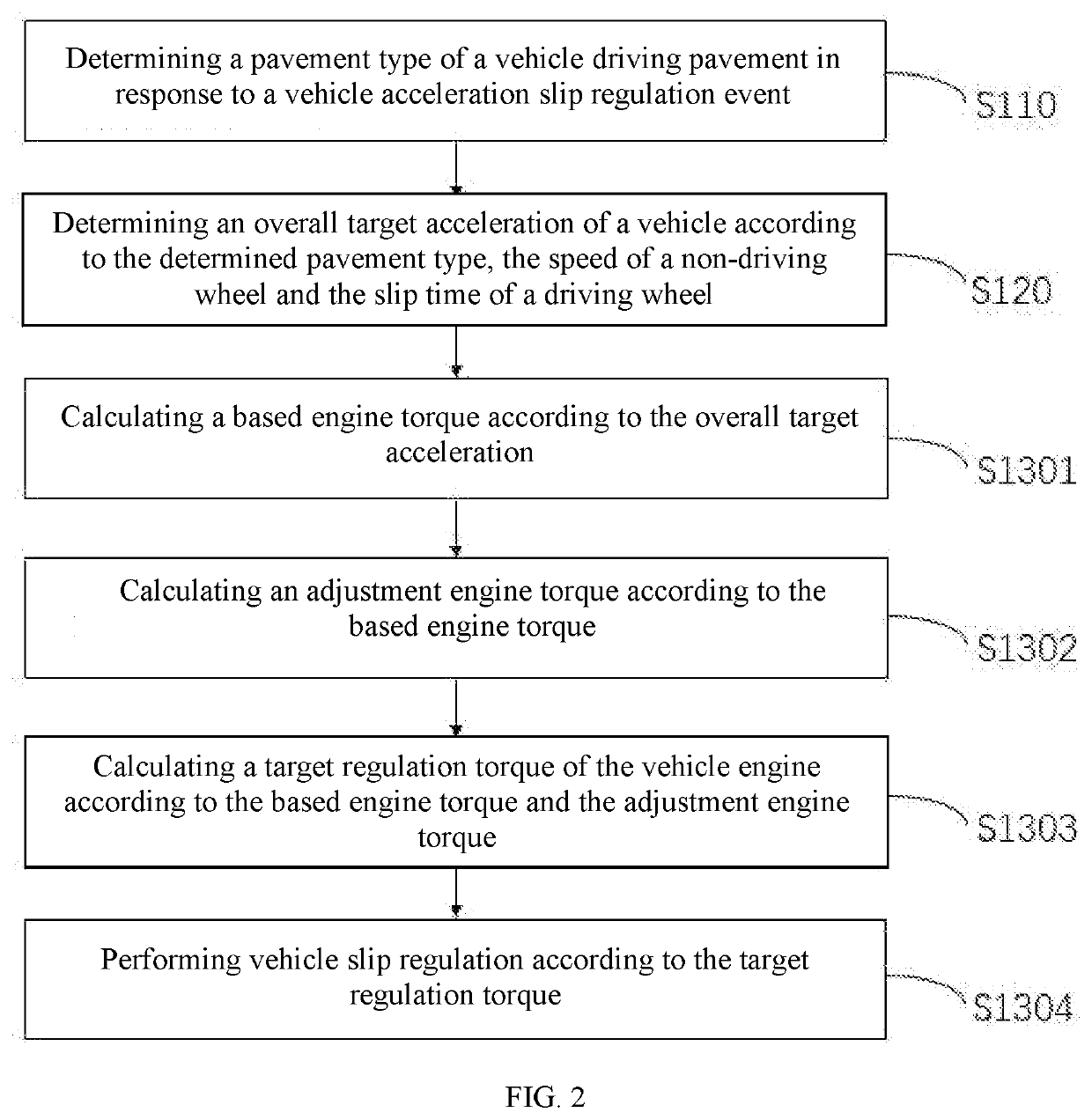
The present invention provides a method and apparatus for regulating the slip of a vehicle. The method involves reducing the engine torque and the braking pressure of the driving wheel on the low adhesion side if the wheel does not slip within a short time. The overall target acceleration of the vehicle is determined based on the pavement type, speed of the non-driving wheel and slip time of the driving wheel, and then the vehicle slip regulation is performed accordingly. This method is not affected by vehicle weight or road slope, making it a practical and robust solution for various non-full-drive vehicles with good slip regulation effect without requiring extensive experimental calibration.

Problems solved by technology

Under extremely bad road conditions such as ice-snow covered pavements and bisectional ice-snow and asphalt adhered pavements, the maximum driving torque that can be provided to driving wheels by the road conditions is less than the driving torque actually acting on the driving wheels, resulting in excessive slip of the driving wheels.
When the slip rate of a vehicle exceeds 20%, the longitudinal adhesion coefficient of the vehicle decreases, while the lateral adhesion coefficient decreases sharply, resulting in insufficient vehicle power, loss of lateral stability, and even heavy loss of life and properties in serious cases.
A large number of test calibrations are required for different vehicle wheel adhesion coefficients of different vehicles, so the practicability and robustness are poor.

Method used


Image

  • Vehicle slip regulation method and apparatus, electronic device and medium
  • Vehicle slip regulation method and apparatus, electronic device and medium
  • Vehicle slip regulation method and apparatus, electronic device and medium

Examples


Embodiment Construction

[0075]Exemplary embodiments of the present application are described below with reference to the accompanying drawings, including various details of the embodiments of the present application to facilitate understanding. The embodiments should be considered as exemplary only. Accordingly, those of ordinary skill in the art should recognize that various changes and modifications can be made to the embodiments described herein without departing from the scope and spirit of the present application. Also, descriptions of well-known functions and constructions are omitted from the following description for clarity and conciseness.

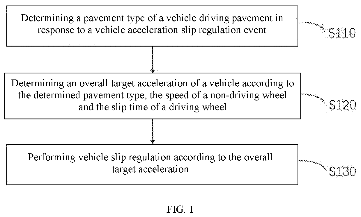
[0076]FIG. 1 is a flowchart of a vehicle slip regulation method provided by an embodiment of the present invention. This embodiment is applicable to the case where slip regulation is performed on a vehicle when wheels slip during the driving of the vehicle. The method may be executed by a vehicle slip regulation apparatus which may be constituted by software and...


PUM


Abstract

The present invention relates to the field of vehicles, in particular to a vehicle slip regulation method and apparatus, an electronic device and a medium. The vehicle slip regulation method comprises the following steps: determining a pavement type of a vehicle driving pavement in response to a vehicle acceleration slip regulation event; determining an overall target acceleration of a vehicle according to the determined pavement type, the speed of a non-driving wheel and the slip time of a driving wheel; and performing vehicle slip regulation according to the overall target acceleration. The method does not need to determine wheel adhesion coefficient of a vehicle according to coefficients such as vehicle weight and road slope, can perform slip regulation by calculating overall target accelerations under different pavements, and has strong practicability and robustness and good acceleration slip regulation effect.

Description

CROSS-REFERENCE TO RELATED APPLICATIONS[0001]This application is a continuation of International Patent Application No. PCT / CN2021 / 124371 with a filing date of Oct. 18, 2021, designating the United States, now pending, and further claims priority to Chinese Patent Application No. 202110115019.0 with a filing date of Jan. 28, 2021. The content of the aforementioned applications, including any intervening amendments thereto, are incorporated herein by reference.TECHNICAL FIELD[0002]The present invention relates to the field of vehicles, in particular to a vehicle slip regulation method and apparatus, an electronic device and a medium.DESCRIPTION OF RELATED ART[0003]Acceleration Slip Regulation (ASR) is one of the key technologies of vehicle active safety. Under extremely bad road conditions such as ice-snow covered pavements and bisectional ice-snow and asphalt adhered pavements, the maximum driving torque that can be provided to driving wheels by the road conditions is less than the ...

Claims


Application Information

Patent Timeline
IPC IPC(8): B60W30/18B60W10/06
CPCB60W30/18172B60W10/06B60W2710/0666B60W2510/0657B60W2510/1005B60W2520/28B60W2520/26B60W2520/105B60W2720/106B60W2520/10B60K28/16B60W2552/40
Inventor XU, XIANJIE
Owner TIANJIN SOTEREA AUTOMOTIVE TECH LMITED CO
Learn More