
CONTROL DEVICE FOR AUTOMATIC TRANSMISSION AND CONTROL METHOD FOR AUTOMATIC TRANSMISSION (as amended)

a technology of automatic transmission and control device, which is applied in the direction of mechanical equipment, transportation and packaging, vehicle fittings, etc., can solve the problems of excessive engine driving force, interruption of constant speed travel mode maintenance, and retardation in fall, so as to suppress the effect of driving force and shorten the time interval

Active Publication Date: 2022-11-03
JATCO LTD +1
View PDF5 Cites 0 Cited by
  • Summary
  • Abstract
  • Description
  • Claims
  • Application Information

AI Technical Summary

Benefits of technology

The automatic transmission described in this patent helps to decrease the force when driving from a slope to a flat road at a constant speed. It does this by controlling the time it takes to shift from one gear to the other. The transmission also reduces the amount of shifting that occurs when driving not at a constant speed, to prevent it from being too treatmenty for the driver.

Problems solved by technology

Accordingly, when implementing the upshift delay control upon upshift in transmission shift position from a lower speed position to a higher speed position in response to transition from slope road travel to flat road travel at the slope travel mode, the delay in upshift results in a retard in fall in engine speed and then a retard in fall in engine driving force, and causes the engine driving force to be excessive in comparison with a driving force required for constant speed travel on the flat road.
This may cause the vehicle to accelerate after the transition to the flat road, and deviate in vehicle speed from a vehicle speed range for the constant speed travel mode, and thereby interrupt maintenance of the constant speed travel mode.

Method used


Image

  • CONTROL DEVICE FOR AUTOMATIC TRANSMISSION AND CONTROL METHOD FOR AUTOMATIC TRANSMISSION    (as amended)
  • CONTROL DEVICE FOR AUTOMATIC TRANSMISSION AND CONTROL METHOD FOR AUTOMATIC TRANSMISSION    (as amended)
  • CONTROL DEVICE FOR AUTOMATIC TRANSMISSION AND CONTROL METHOD FOR AUTOMATIC TRANSMISSION    (as amended)

Examples


Embodiment Construction

[0018]The following describes an embodiment of a control device for an automatic transmission, with reference to the drawings. The embodiment is merely an example, and is not intended to exclude various modifications or various arts inexplicit in the embodiment. Each of configurations in the embodiment may be variously modified and carried out within scope of the invention. It is also allowed to sift and / or combine the configurations as appropriate.

1. Overall System Configurations

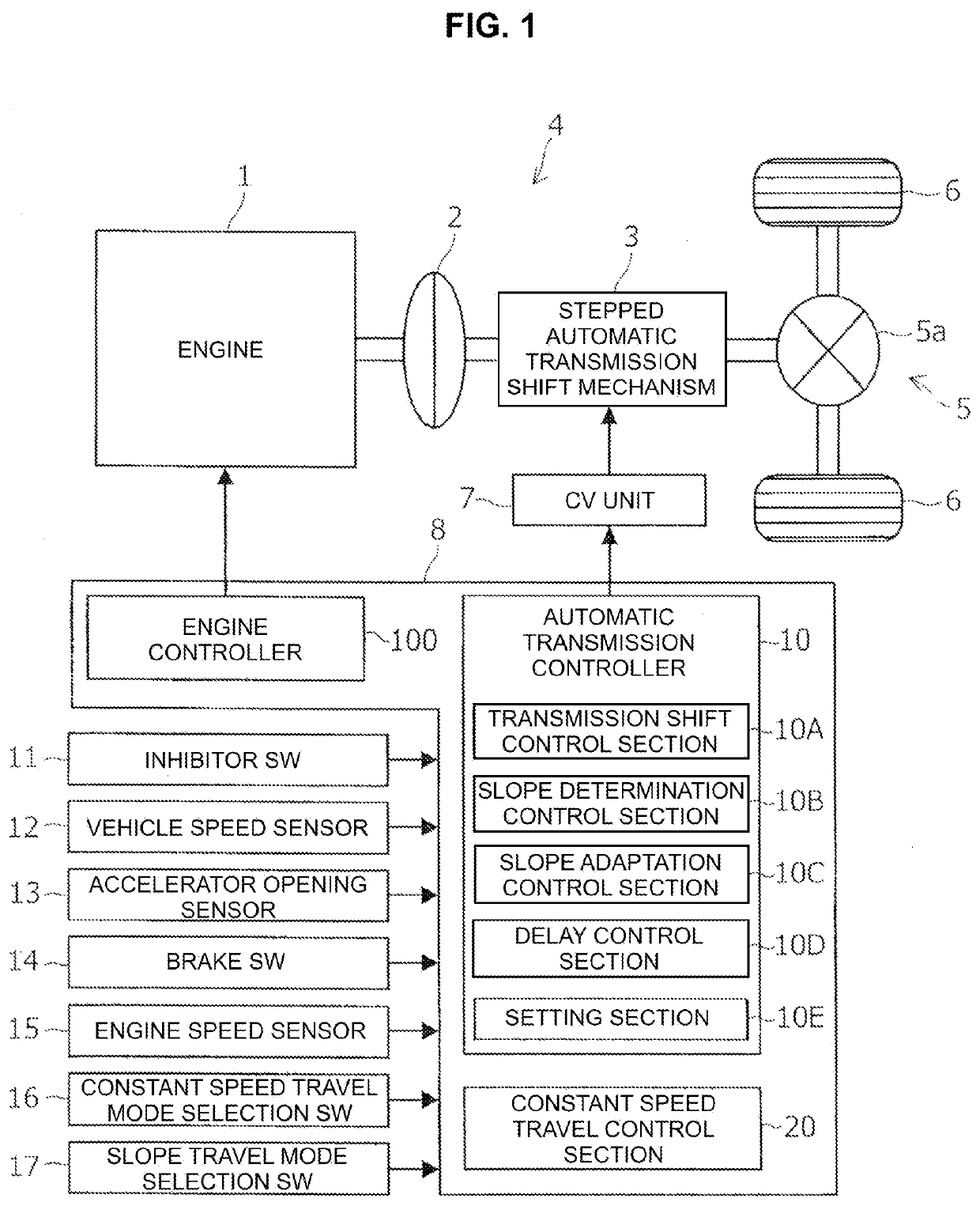
[0019]FIG. 1 shows a power train of a vehicle according to the present embodiment. The power train includes an engine 1 (i.e., a driving prime mover), an automatic transmission 4 (i.e., a stepped automatic transmission), and a power transmission mechanism 5. The automatic transmission 4 includes a torque converter 2 including a lock-up clutch and an automatic transmission shift mechanism 3 of stepped type. The power transmission mechanism 5 includes a differential mechanism 5a disposed between an output sha...


PUM


Abstract

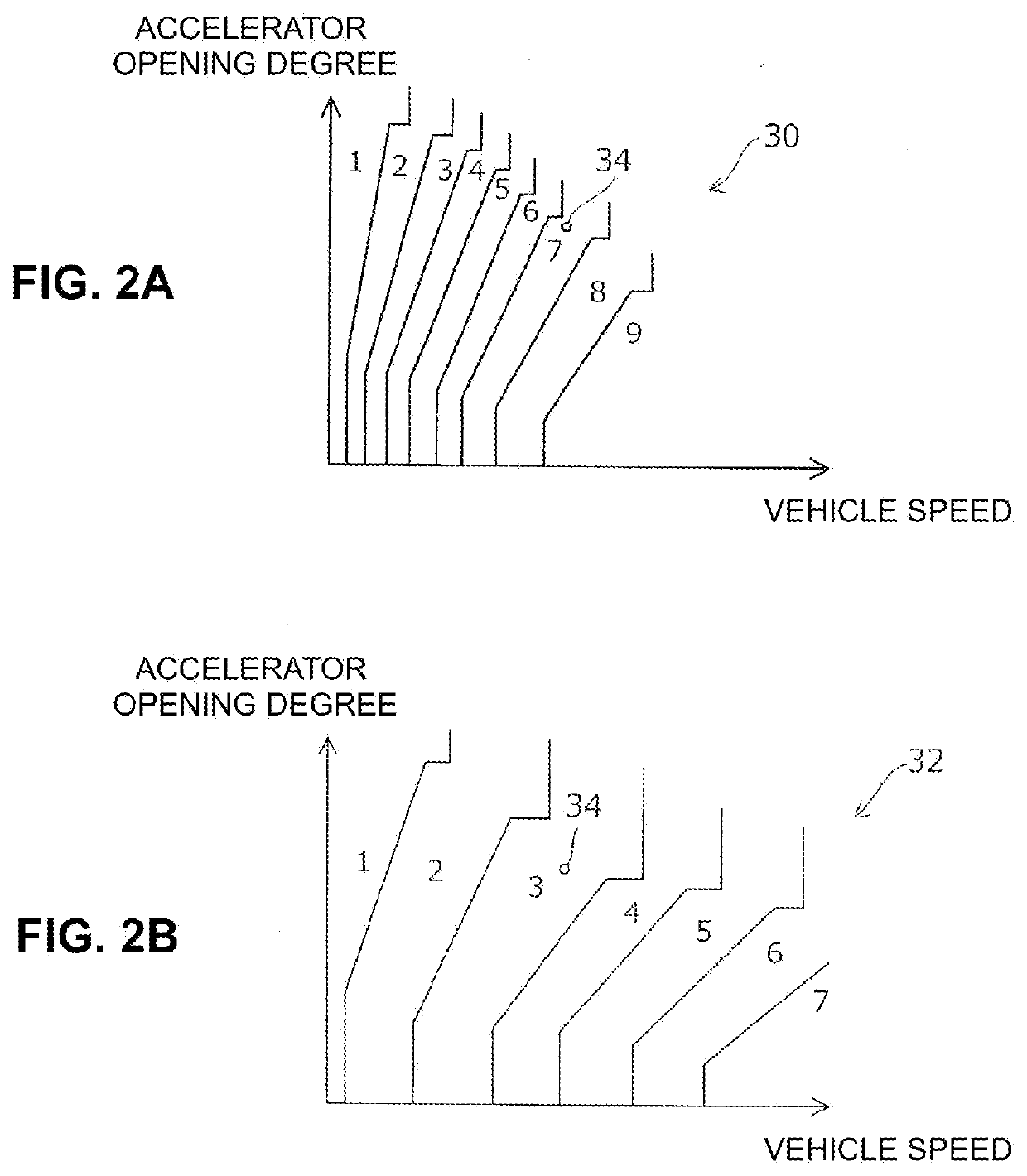
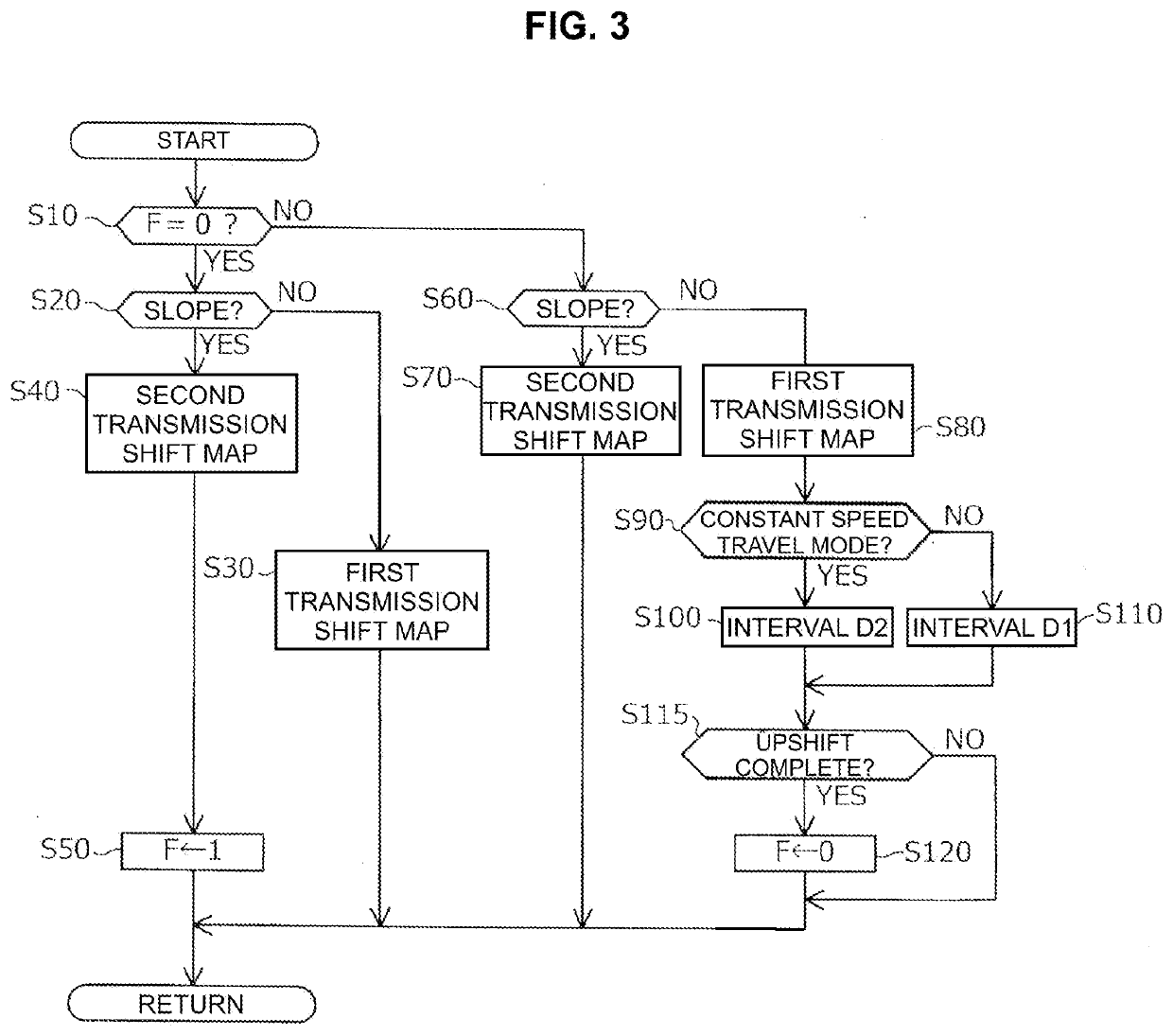
A control device for an automatic transmission in a vehicle with a constant speed travel mode includes: a determination section that determines whether the vehicle is traveling on a slope road; a slope adaptation control section that implements a first transmission shift control if not traveling on a slope road and, if traveling on a slope road, implements a second transmission shift control for selecting a transmission shift position of a lower speed than case of not traveling on a slope road; a delaying section that, upon switching from the second transmission shift control to the first transmission shift control, implements an upshift delay control for performing upshift one by one at a predetermined time interval; and a setting section that, in case of traveling at the constant speed travel mode, sets the time interval shorter in comparison with case of traveling not at the constant speed travel mode.

Description

TECHNICAL FIELD[0001]The present invention relates to a control device for an automatic transmission installed in a vehicle that has a constant speed travel mode.BACKGROUND ART[0002]Patent Document 1 discloses a vehicle control device that has a first travel mode and a second travel mode. The first travel mode is a travel mode to perform transmission shift control on an automatic transmission and driving force control, in accordance with acceleration and deceleration operation by a driver. The second travel mode is a travel mode to set a target travel condition such as a target vehicle speed, and perform transmission shift control and driving force control independently of the acceleration and deceleration operation by a driver: i.e., so-called a constant speed travel mode. The second travel mode includes control to suppress frequent implementation of transmission shift, in order to avoid busy shift. In addition, the constant speed travel mode is normally brought to forcible termina...

Claims


Application Information

Patent Timeline
Patent Type & Authority Applications(United States)
IPC IPC(8): F16H59/44F16H59/66F16H61/02
CPCF16H59/44F16H59/66F16H61/0213F16H2059/663F16H2061/0234B60K31/00F16H63/50F16H2061/0227
Inventor HIRASAKO, KAZUKI
Owner JATCO LTD
Learn More