Optical Connecting Structure

a coupling structure and optical technology, applied in the field of optical coupling structure, can solve the problems of reducing the coupling cost affecting the coupling effect of etc., to achieve the effect of reducing the coupling cost and reducing the coupling between optical elements and optical fibers

Pending Publication Date: 2022-11-03
NIPPON TELEGRAPH & TELEPHONE CORP
View PDF0 Cites 0 Cited by
  • Summary
  • Abstract
  • Description
  • Claims
  • Application Information

AI Technical Summary

Benefits of technology

[0016]According to embodiments of the present invention, by making both the contact angle which the surface of the optical element and the surface of the adhesive agent make and the contact angle which the surface of the optical fiber and the surface of the adhesive agent make less than 90...

Problems solved by technology

However, optical signal processing technology has some problems compared to electronic circuit technology.
On the other hand, in optical signal processing technology, in the case of a spatial optical system, a size of system becomes extremely large.
Accordingly, the optical signal processing technology is liable to require a large device size compared to electronic circuit te...

Method used


Image

  • Optical Connecting Structure
  • Optical Connecting Structure
  • Optical Connecting Structure

Examples


first embodiment

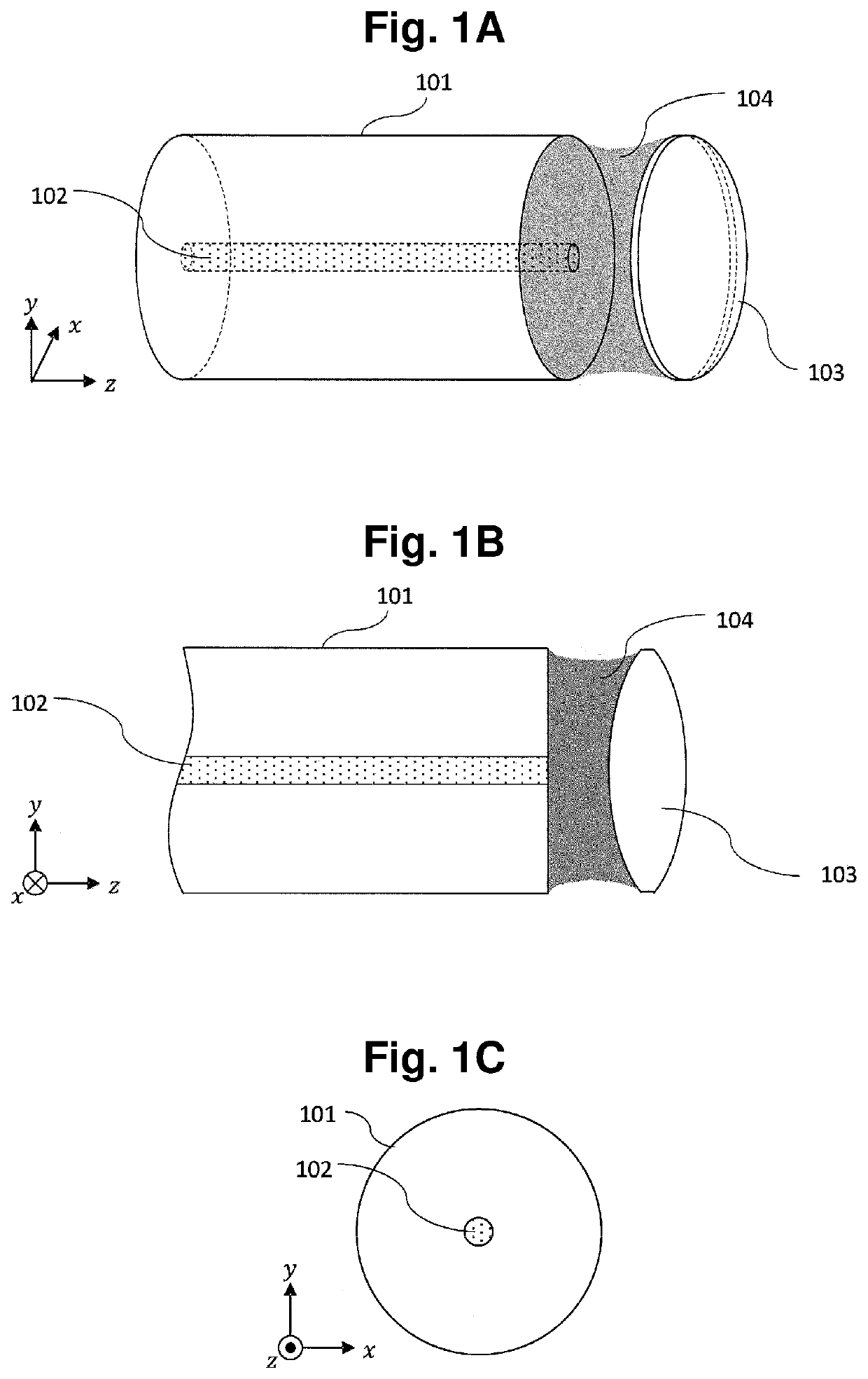
[0047]As shown in FIG. 1A to FIG. 1D, an optical coupling structure according to a first embodiment of the present invention is an optical coupling structure where a lens 103 and an optical fiber 101 are coupled to each other by an adhesive agent 104. An optical fiber core 102 is formed in the optical fiber 101. The adhesive agent 104 is applied to a surface of the lens 103 which faces the optical fiber 101 and an end surface of the optical fiber 101 which faces the lens. By adhering the lens 103 to the end surface of the optical fiber 101 by the adhesive agent 104, the optical fiber 101 and the lens 103 are coupled to each other optically and mechanically by the adhesive agent 104.

[0048]As shown in FIG. 1A and FIG. 1B, both a contact angle which the surface of the lens 103 and a surface of the adhesive agent 104 make and a contact angle which the end surface of the optical fiber 101 and the surface of the adhesive agent 104 make are less than 90 degrees.

[0049]With such a structure,...

second embodiment

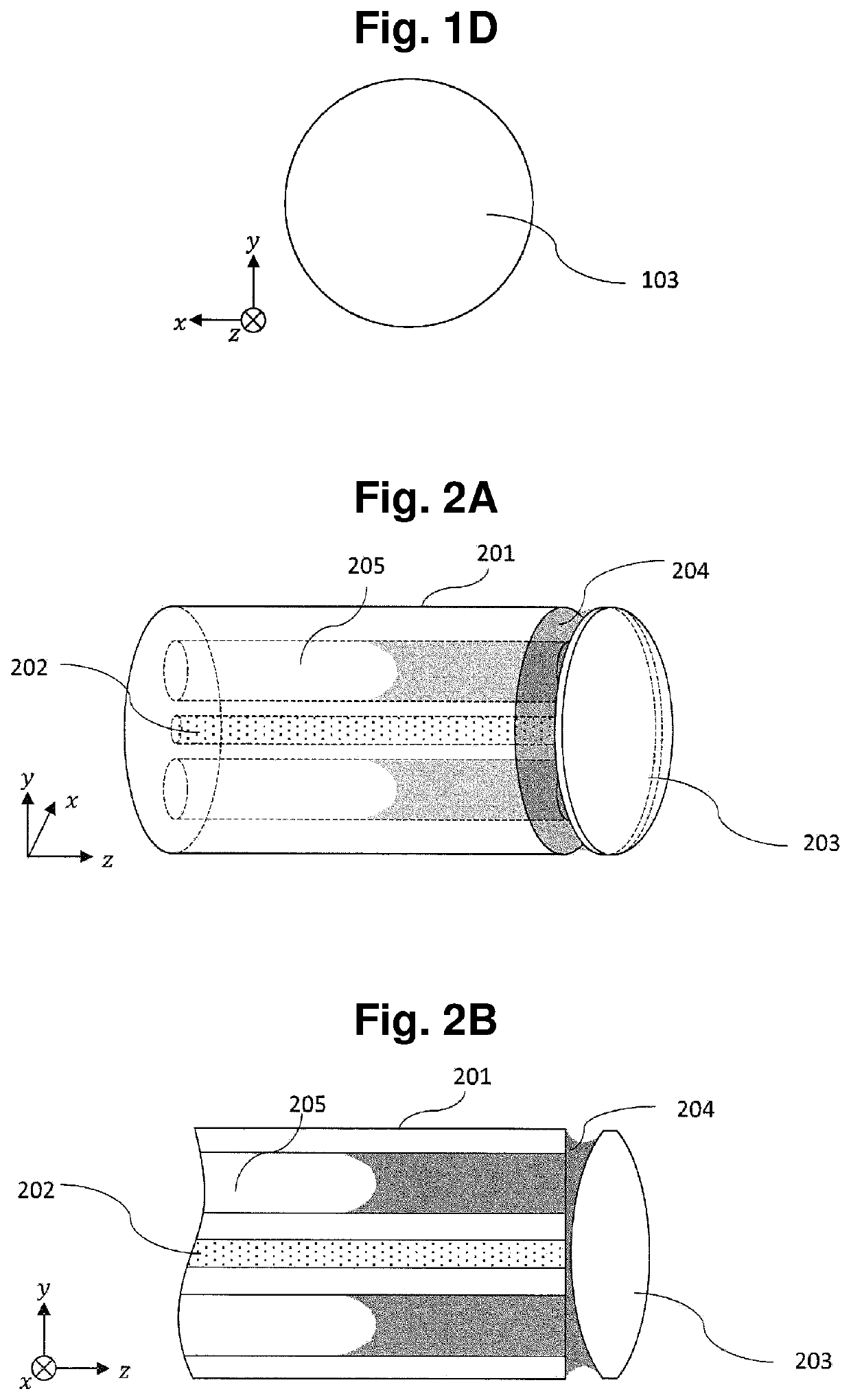
[0052]An optical coupling structure according to a second embodiment is an optical coupling structure where a lens 203 and an optical fiber 101 are coupled to each other by an adhesive agent 104 in the same manner as the optical coupling structure according to the first embodiment described above. As shown in FIG. 2A to FIG. 2C, the optical fiber 201 in the optical coupling structure according to the second embodiment is a so-called hole-formed optical fiber which includes holes 205 opening at an end surface in addition to an optical fiber core 202.

[0053]In this embodiment, the hole-formed optical fiber 201 includes, as the holes 205, hollow holes having a columnar shape which are formed in a clad portion parallel to the optical fiber core 202. That is, the hole-formed optical fiber 201 includes the hollow holes having a columnar shape which are formed parallel to a waveguide direction of the optical fiber 201. As shown in FIG. 2A to FIG. 2C, in this embodiment, as viewed from a z d...

third embodiment

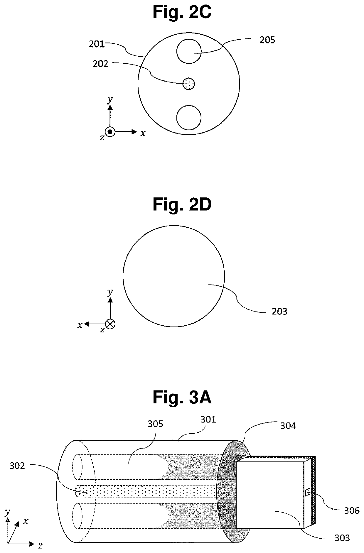
[0061]As shown in FIG. 3A to FIG. 3E, an optical coupling structure according to a third embodiment of the present invention is a structure where a hole-formed optical fiber 301 and a PLC 303 are coupled to each other by an adhesive agent 304.

[0062]The configuration of the hole-formed optical fiber 301 is equal to the configuration of the hole-formed optical fiber 201 according to the second embodiment. That is, the optical fiber 301 includes, as holes 305, two hollow holes having a circular columnar shape formed parallel to an optical fiber core 302. That is, the optical fiber 301 includes two hollow holes having a circular columnar shape formed along a waveguide direction of the optical fiber 301. Two holes are formed at symmetrical positions with respect to the optical fiber core 302 as viewed from a y direction as shown in FIG. 3C.

[0063]On the other hand, as shown in FIG. 3A, FIG. 3B and FIG. 3E, a PLC core 306 is formed in the PLC 303.

[0064]As shown in FIG. 3B, in the optical c...


PUM


Abstract

An embodiment optical coupling structure includes: at least one optical element; at least one optical fiber which has an end surface facing the optical element; and an adhesive agent which is applied to at least the end surface and a part of the optical element so as to optically and mechanically couple the optical element and the optical fiber, wherein both a contact angle which a surface of the optical element and a surface of the adhesive agent make and a contact angle which a surface of the optical fiber and the surface of the adhesive agent make are less than 90 degrees. With such a configuration, alignment between the optical element and the optical fiber can be realized by passive alignment so that a mounting time and a mounting cost in coupling the optical element and the optical fiber can be reduced.

Description

CROSS-REFERENCE TO RELATED APPLICATION[0001]This application is a national phase entry of PCT Application No. PCT / JP2019 / 024731, filed on Jun. 21, 2019, which application is hereby incorporated herein by reference.TECHNICAL FIELD[0002]The present invention relates to an optical coupling structure, and more specifically to an optical coupling structure between an optical element and an optical fiber.BACKGROUND ART[0003]An industrial field which uses optical signal processing technology such as optical communication or optical sensing has been in rapid and continuous progress with its related fields. Electronic circuit technology has been in rapid and continuous progress as in optical signal processing technology and is often used in combination with the optical signal processing technology. However, optical signal processing technology has some problems compared to electronic circuit technology. These are compacting and convenient coupling.Compacting[0004]In electronic circuit techno...

Claims


Application Information

Patent Timeline
IPC IPC(8): G02B6/30
CPCG02B6/30G02B6/32G02B6/02385
Inventor ISHIKAWA, HIROSHIABE, MAKOTOSATO, NORIOARATAKE, ATSUSHI
Owner NIPPON TELEGRAPH & TELEPHONE CORP
Why Eureka
Try Eureka