Eureka AIR delivers breakthrough ideas for toughest innovation challenges, trusted by R&D personnel around the world.

Display panel and display device

Pending Publication Date: 2022-11-03
TCL CHINA STAR OPTOELECTRONICS TECH CO LTD
View PDF2 Cites 0 Cited by
  • Summary
  • Abstract
  • Description
  • Claims
  • Application Information

AI Technical Summary

Benefits of technology

The present invention provides a display panel and device that use a logic controller to generate multiple enable signals with sequentially changing phases. This reduces the load capacity of the source driver chip, which lowers costs. The time-sharingly output of the source driver chip also reduces peak current, power consumption, and the risk of EMI.

Problems solved by technology

This not only requires a source driver with a higher load capacity, but also increases power consumption of the source driver and increases the risk of serious electromagnetic interference (EMI).

Method used


Image

  • Display panel and display device
  • Display panel and display device
  • Display panel and display device

Examples


Embodiment Construction

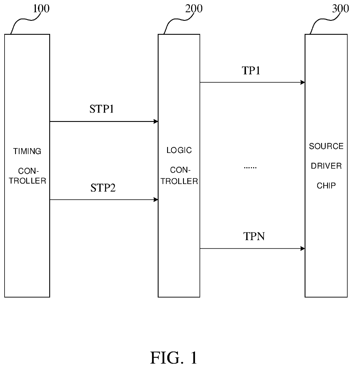
[0018]As shown in FIG. 1, the present embodiment provides a display panel, which comprises a timing controller 100, a logic controller 200, and at least one source driver chips 300. The timing controller 100 outputs a generated first enable sub-signal STP1 and a generated second enable sub-signal STP2 to two input terminals of the logic controller 200. The logic controller 200 generates N number of enable signals with sequentially changing phases according to the first enable sub-signal STP1 and the second enable sub-signal STP2. For example, a first enable signal TP1 to the Nth enable signal TPN. The N number of enable signals are output to at least one source driver chip 300, and the source driver chip 300 controls data signals in all output channels according to the corresponding enable signals, so as to time-sharingly output the enable signals in N number of sets. N is an integer greater than or equal to 2.

[0019]It should be noted that, a number of the source driver chips 300 ca...


PUM


Abstract

The present invention provides a display panel and a display device. The first enable sub-signal and the second enable sub-signal output by the timing controller are modulated by the logic controller to generate a plurality of enable signals with sequentially changing phases, which can control data signals in a source driver chip to time-sharingly output by multiple sets. This reduces a load capacity of the source driver chip, which is beneficial to reducing costs of the source driver chip. The time-sharing output of the source driver chip can reduce a peak current of each output channel, thus reducing power consumption and lowering the risk of electromagnetic interference (EMI).

Description

FIELD OF INVENTION[0001]The present invention relates to the field of display technology and in particular to the field of data driving technology, specifically to a display panel and a display device.BACKGROUND OF INVENTION[0002]In traditional technical solutions, a timing controller controls a source driver to output data signals of all channels to corresponding data lines at the same time through an enable signal, resulting in currents of each data signal in the source driver peaking at the same time. This not only requires a source driver with a higher load capacity, but also increases power consumption of the source driver and increases the risk of serious electromagnetic interference (EMI).SUMMARY[0003]The present invention provides a display panel and a display device, which solves the problem below: a source driver chip controlled by a timing controller to output all data signals at the same time requires a higher loading capacity, an issue of power consumption, and the risk...

Claims


Application Information

Patent Timeline
IPC IPC(8): G09G3/20
CPCG09G3/2092G09G2310/08G09G2310/0275G09G2330/06G09G2330/021G09G3/20G09G2370/08
Inventor LIU, JINFENG
Owner TCL CHINA STAR OPTOELECTRONICS TECH CO LTD
Why Eureka
Eureka Blog
Learn More