
Support element for portions of meat

Pending Publication Date: 2022-11-10
FAVA DI ADELE TURETTA & C
View PDF6 Cites 0 Cited by
  • Summary
  • Abstract
  • Description
  • Claims
  • Application Information

AI Technical Summary

Benefits of technology

The invention provides a support element that can be pulled or held in place during the process of extracting meat, rather than pushed. This solution avoids the problems of the prior art due to overlapping of meat portions. The positioning of the appendage and the distribution of the sections over a high longitudinal portion of the appendage allow for a better distribution of force applied to the support element, resulting in a thinner and lighter support element that is less expensive and more compact for the same weight of meat to be supported compared to known support elements. This allows for a particularly robust support element suitable for rapid series production.

Problems solved by technology

This can be very complicated when the portions of meat are rigid, for example as a result of smoking and / or freezing.
In particular, although the pad is configured to act in a portion of the connection body proximal to the bar, which should be free from the portion of meat, since the shape of such portions of meat is not always regular, it may occur that if a portion of meat protrudes towards the bar more than normal, when the pad is actuated this excessively protruding portion of meat remains squashed between the pad and the connection body, thus preventing the support element from being detached from the portion of meat.
Making longer connection bodies of the support elements so that the needles are further away from the bar is not an easy solution, as this would increase the weight of the support elements, which would have an impact on the energy required to move the support elements along the plant (which are generally several thousand in number), as well as on the costs of making the support elements themselves.
Another problem is that acting on the connection body near the bar requires a high force, particularly if the piece of meat is rigid, in order to allow the needles to be removed from the portion of meat.
Consequently, to withstand these strains, the support elements have to be very thick, which makes them particularly heavy.
This has an impact on the energy required to move the support elements along the plant, as well as the manufacturing costs.

Method used


Image

  • Support element for portions of meat
  • Support element for portions of meat
  • Support element for portions of meat

Examples


Embodiment Construction

[0077]FIG. 35 shows a schematic example of an automated processing plant 1 for processing portions of meat 10 such as bacon.

[0078]Such automated plant 1 comprises an automated loading station 15 for the portions of meat, which is configured to load, i.e. hook, the portions of meat 10 onto support elements (FIGS. 6, 16-34). In particular, as will be described below, these support elements are equipped with hooks and the loading station is configured to insert these hooks into the portions of meat to secure them to the support element.

[0079]Depending on the size of the portion of meat and the support element, i.e. the number of hooks, one or more portions of meat can be attached to a single support element.

[0080]The portions of meat are preferably elongated and irregular in shape, with two dimensions (width and height) prevailing over a third dimension (thickness), and in which it is therefore possible to identify a first greater face 20 and a second greater face 25 opposite the first...


PUM


Abstract

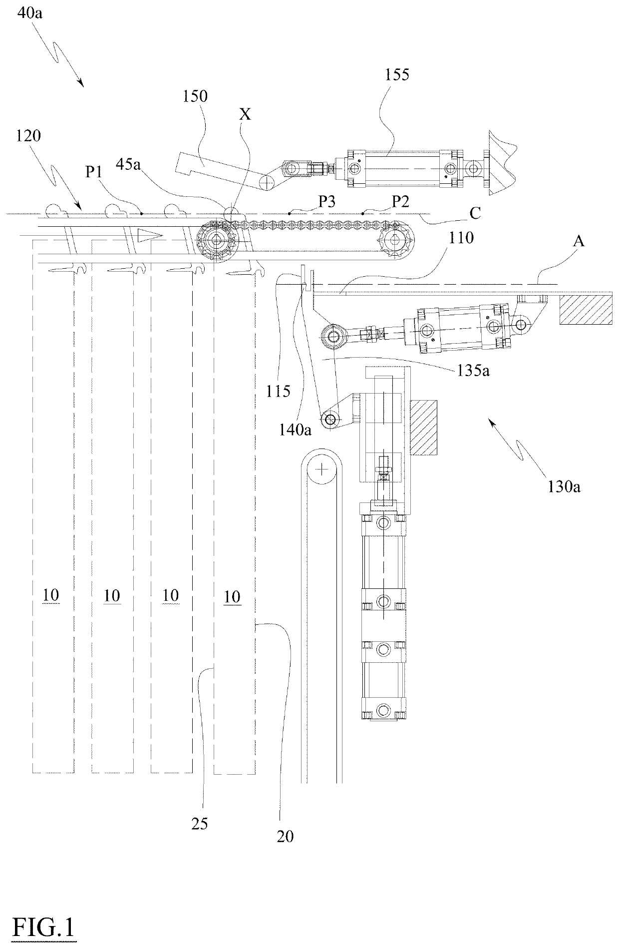
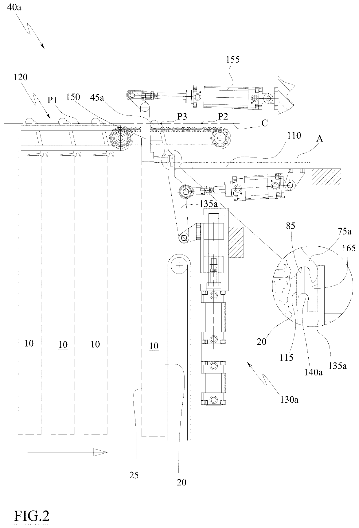
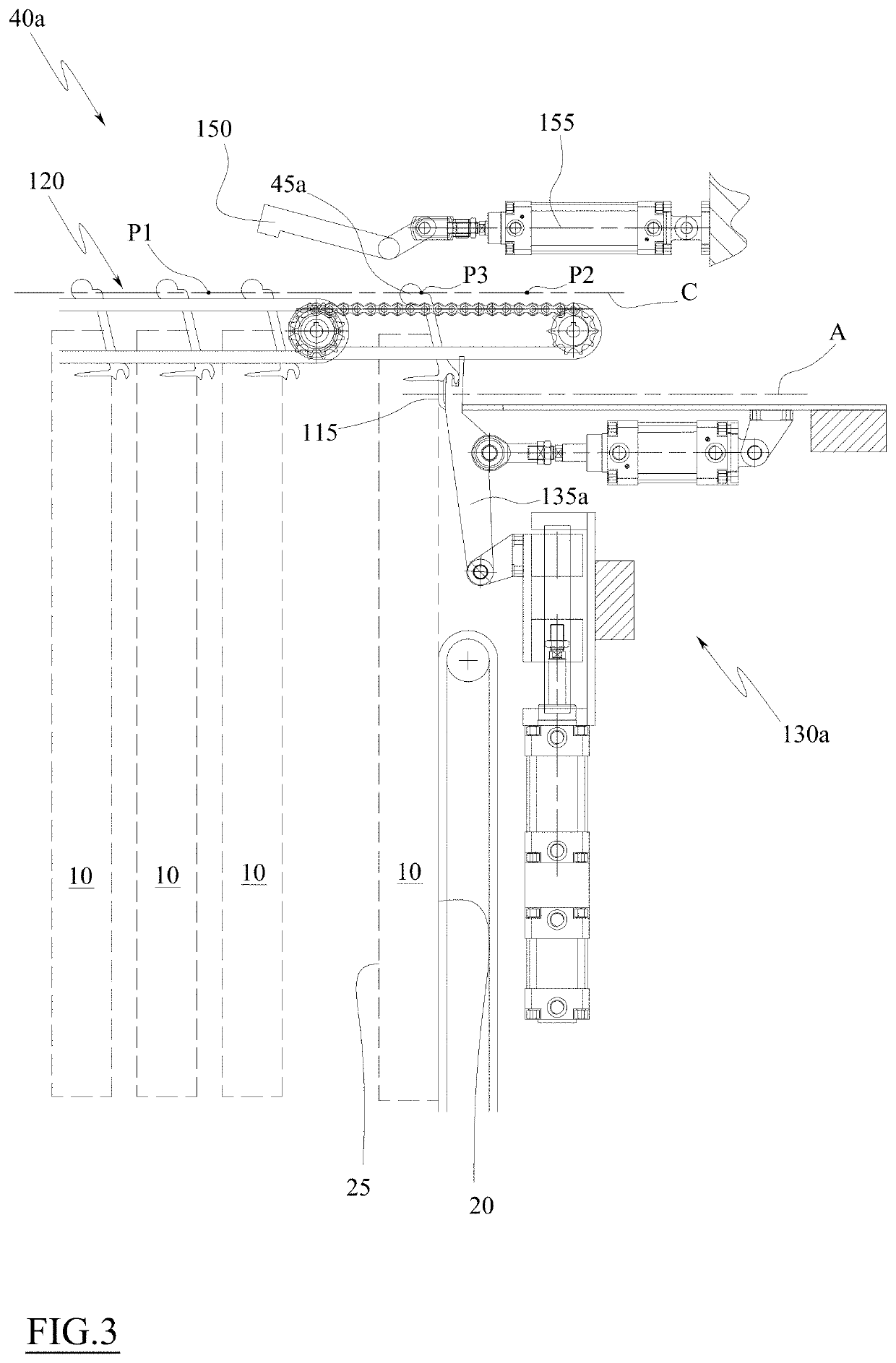
A support element (45a,45b,45c,45d,45e,45f,45g,45h,45i,45l,45m,45n) is described for a portion of meat (10), adapted to hook said portion of meat and to allow the handling of said portion of meat, said support element comprising: a bar (50a,50b,50c,50d,50e,50f,50g,50h,50i,50l,50m,50n) developing longitudinally along a longitudinal axis (X), a plurality of straight needles (55), adapted to penetrate the portion of meat (10), arranged with longitudinal axes (K) parallel to each other and arranged in a row parallel to the longitudinal axis (X), a connection body (60a,60b,60c,60d,60e) connecting the straight needles to the bar and comprising a first face (65a,65b,65c,65d,65e), from which said needles (55) rise, and a second face (70a,70b,70c,70d,70e) facing in the opposite direction to the first face. Wherein said support element comprises: a grasping appendage (75a,75b,75c,75d,75e), which rises from a portion of the second face (70a,70b,70c,70d,70e) proximal to the needles (55) and develops both in a direction away from the first face and from the second face and in a longitudinal direction parallel to the longitudinal axis (X) of the bar (50a,50b,50c,50d,50e,50f,50g,50h,50i,50l,50m,50n). Wherein said grasping appendage (75a,75b,75c,75d,75e) is rigidly integral with the second face (70a,70b,70c,70d,70e) in at least a plurality of side-by-side sections along said longitudinal direction along which the grasping appendage develops, and wherein there is at least one of said sections every two consecutive needles (55).

Description

TECHNICAL FIELD[0001]The invention belongs to the technical field of plants for processing portions of meat, for example bacon, wherein said portions of meat are, for example, cured and / or frozen and / or smoked and / or cooked and / or chilled.[0002]More specifically, the present invention relates to a support element for such portions of meat.PRIOR ART[0003]There are known plants for processing portions of meat, for example cuts of meat of elongated and irregular shape in which two dimensions (width and height) are prevalent with respect to a third dimension (thickness). A typical cut of meat of that type is bacon.[0004]These plants comprise stations for processing portions of meat, for example smoking stations, salting stations, seasoning stations, cooking stations, refrigeration / freezing stations, etc. In particular, plants for processing bellies generally comprise at least one smoking station and a refrigeration / freezing station.[0005]The portions of meat are moved within the process...

Claims


Application Information

Patent Timeline
Patent Type & Authority Applications(United States)
IPC IPC(8): A22C15/00
CPCA22C15/005
Inventor FAVA, ANTONIO
Owner FAVA DI ADELE TURETTA & C
Learn More