Sensor Arrangement and Method for Joining a Sensor Arrangement of this kind

Pending Publication Date: 2022-11-10
ROBERT BOSCH GMBH
View PDF0 Cites 2 Cited by
  • Summary
  • Abstract
  • Description
  • Claims
  • Application Information

AI Technical Summary

Problems solved by technology

When controlled correctly, this achieves higher rotational speeds with the result that the braking pressure in the vehicle can be built up quicker, which in the end effect leads to a shortening of the braking distance.

Method used


Image

  • Sensor Arrangement and Method for Joining a Sensor Arrangement of this kind
  • Sensor Arrangement and Method for Joining a Sensor Arrangement of this kind
  • Sensor Arrangement and Method for Joining a Sensor Arrangement of this kind

Examples


Embodiment Construction

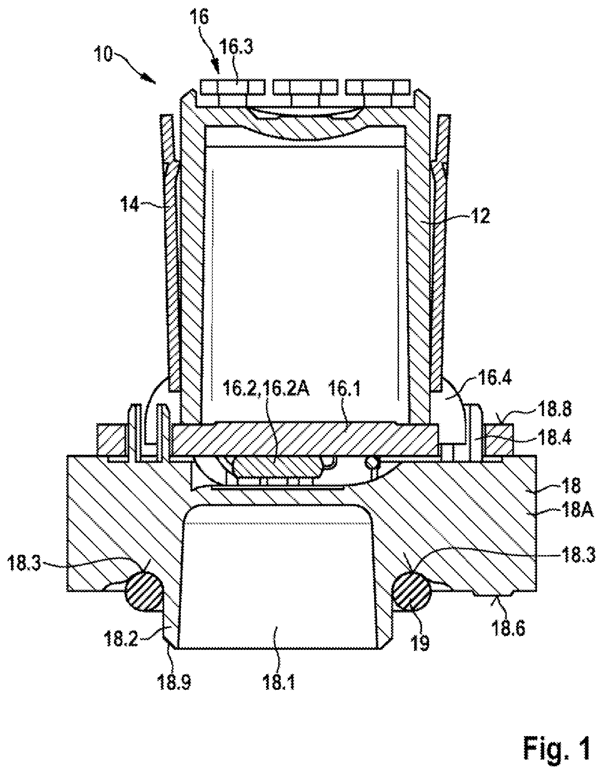
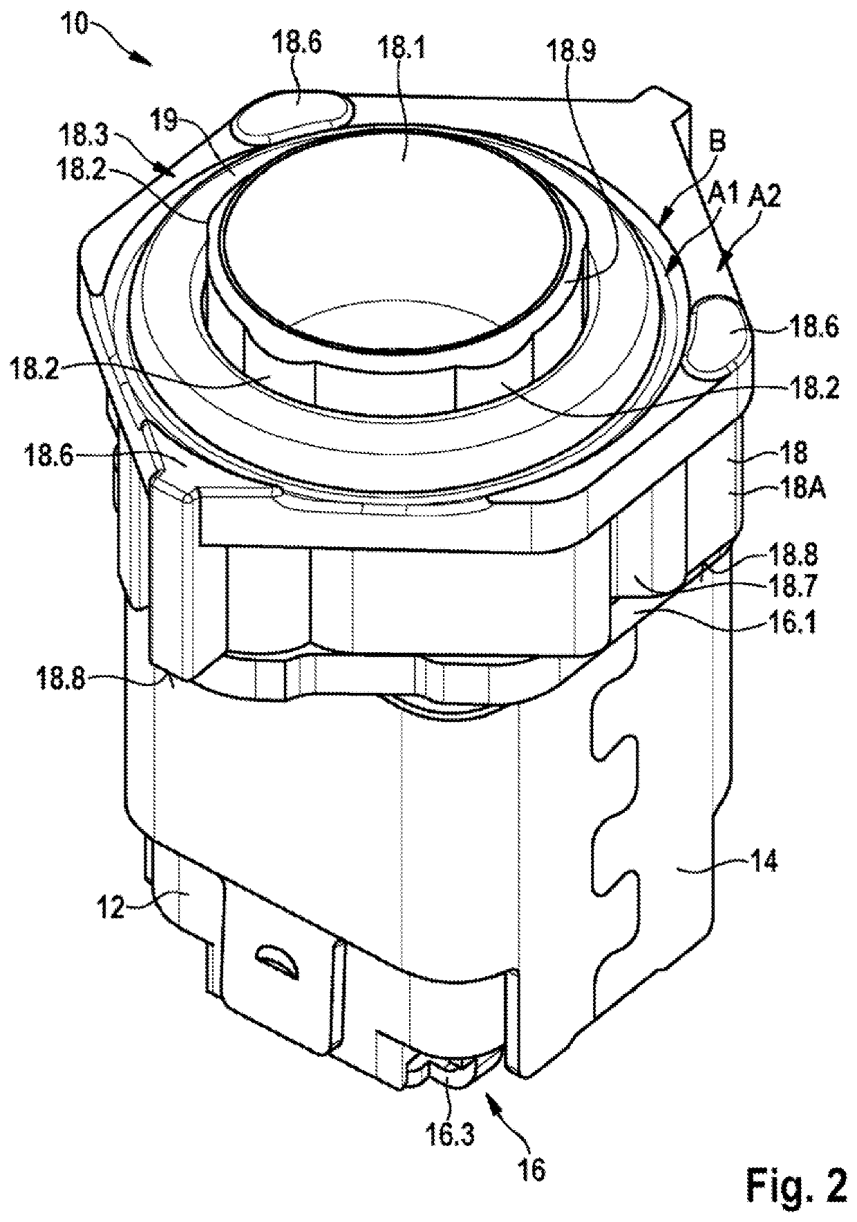
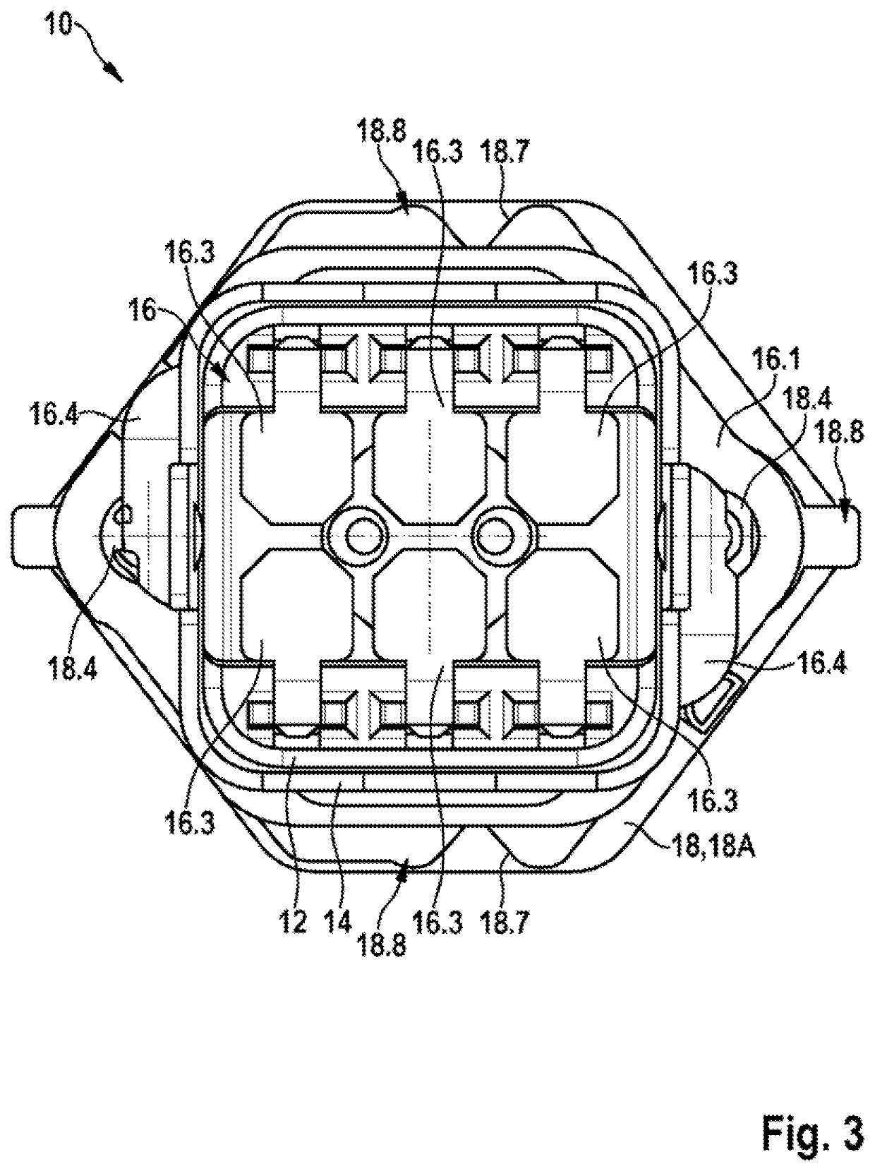
[0031]As is apparent from FIGS. 1 to 5, the illustrated exemplary embodiment of a sensor arrangement 1 in accordance with the invention for the contactless detection of a movement of a body 26 that is movably mounted within a first housing 3 comprises a transducer 20, which is non-rotatably connected to the body 26 and moves simultaneously with the body 26, and a measuring apparatus 10 that is fixedly arranged and comprises a measuring element 16.2. In dependence upon the movement of the body 26, the transducer 20 influences at least one physical variable that is detected by the measuring element 16.2. In so doing, the measuring apparatus 10 is connected to the first housing 3 by way of a connecting adapter 18 that is designed in the illustrated embodiment as a synthetic material injection part 18A. The connecting adapter 18 comprises on a side that is facing the first housing 3 a circumferential receiving contour 18.3 in which a silicone bead 19 is inserted and pressed between the ...


PUM


Abstract

A sensor arrangement for detecting in a contactless manner a movement of a body that is movably mounted within a housing includes the housing, a transducer configured to be non-rotatably connected to the body and move simultaneously with the body, and a measuring apparatus that is fixedly arranged and comprises a measuring element. When the body is movably mounted in the housing, the transducer is configured, in dependence upon the movement of the body, to influence at least one physical variable that is detected by the measuring element, the measuring apparatus is connected to the first housing by way of a connecting adapter that includes, on a side that is facing the first housing, a circumferential receiving contour into which a silicone bead is introduced and pressed in between the receiving contour and the housing, and the silicone bead (fixes and seals the connecting adapter on the housing.

Description

[0001]The invention relates to a sensor arrangement for detecting a movement of a body that is movably mounted within a first housing and a method for joining such a sensor arrangement. Subject matter of the present invention is also an ESP system (ESP: electronic stability program) for a vehicle having such a sensor arrangement.[0002]In the case of an improved ESP system, a brushless DC motor that is also described as a brushless EC motor (electronically commutated motor) is to be used in lieu of a simple DC motor. When controlled correctly, this achieves higher rotational speeds with the result that the braking pressure in the vehicle can be built up quicker, which in the end effect leads to a shortening of the braking distance. In order to activate the motor at the correct point in time, a sensor arrangement is installed, which recognizes the prevailing rotational position of the motor and transmits this position to a control device. For this purpose, a transducer that is designe...

Claims


Application Information

Patent Timeline
Patent Type & Authority Applications(United States)
IPC IPC(8): B60T13/66B60T8/36H02K11/01
CPCB60T13/662B60T8/368H02K11/0141B60T2270/30H02K11/215G01D11/245
Inventor JOERG, MARTINHOFMANN, DIETMARBIGL, PETER
Owner ROBERT BOSCH GMBH
Why Eureka
Try Eureka