Polluted range locating apparatus and computer readable medium

Pending Publication Date: 2022-11-10
MITSUBISHI ELECTRIC CORP
View PDF0 Cites 0 Cited by
  • Summary
  • Abstract
  • Description
  • Claims
  • Application Information

AI Technical Summary

Benefits of technology

[0017]According to the present disclosure, locating a polluted range such as an intrusion route and a polluted part will be possible.

Problems solved by technology

First, a cyberattack on a monitoring target is detected.

Method used


Image

  • Polluted range locating apparatus and computer readable medium
  • Polluted range locating apparatus and computer readable medium
  • Polluted range locating apparatus and computer readable medium

Examples


embodiment 1

[0031]A polluted range locating apparatus 100 will be described based on FIG. 1 to FIG. 7.

[0032]Description of Configuration

[0033]A configuration of the polluted range locating apparatus 100 will be described based on FIG. 1.

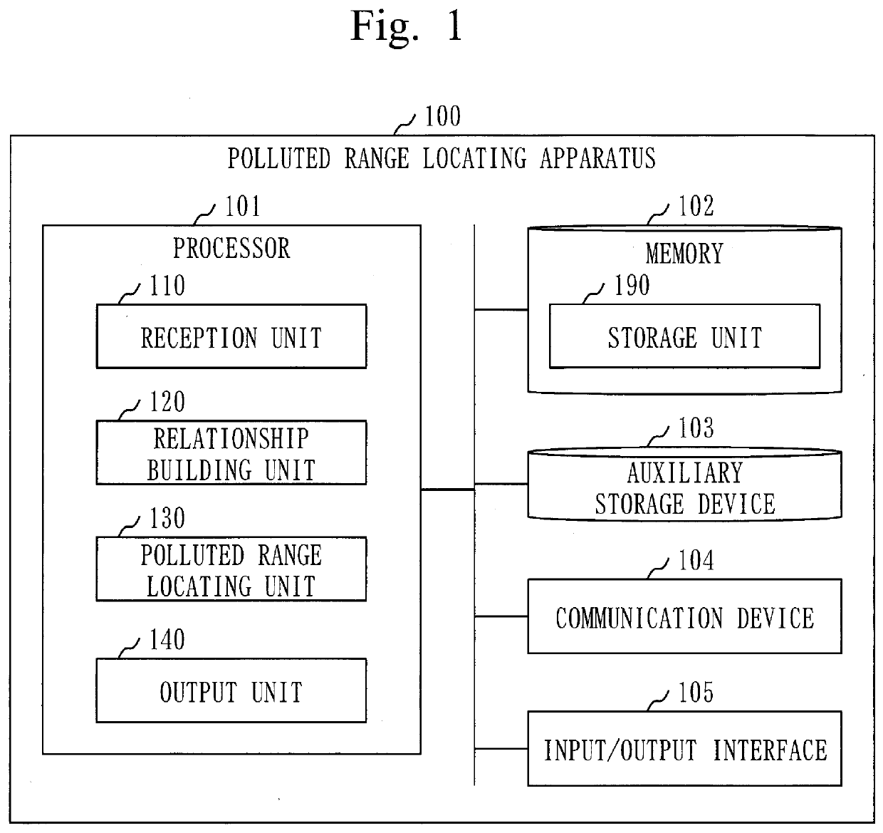
[0034]The polluted range locating apparatus 100 is a computer that includes hardware such as a processor 101, a memory 102, an auxiliary storage device 103, a communication device 104, and an input / output interface 105. These hardware are connected to each other by signal lines.

[0035]The processor 101 is an IC that performs a calculation process and controls other hardware. For example, the processor 101 is a CPU, a DSP, or a GPU.

[0036]IC is an abbreviated name for Integrated Circuit.

[0037]CPU is an abbreviated name for Central Processing Unit.

[0038]DSP is an abbreviated name for Digital Signal Processor.

[0039]GPU is an abbreviated name for Graphics Processing Unit.

[0040]The memory 102 is a volatile or a non-volatile storage device. The memory 102 is also called...

example 1

[0148]In step S111, the reception unit 110 accepts log data that indicates Process End.

[0149]In step S112, the relationship building unit 120 extracts the operation type and the operation object information from the log data. The operation type is Process End. The operation object is an instruction process, and the target object is end process.

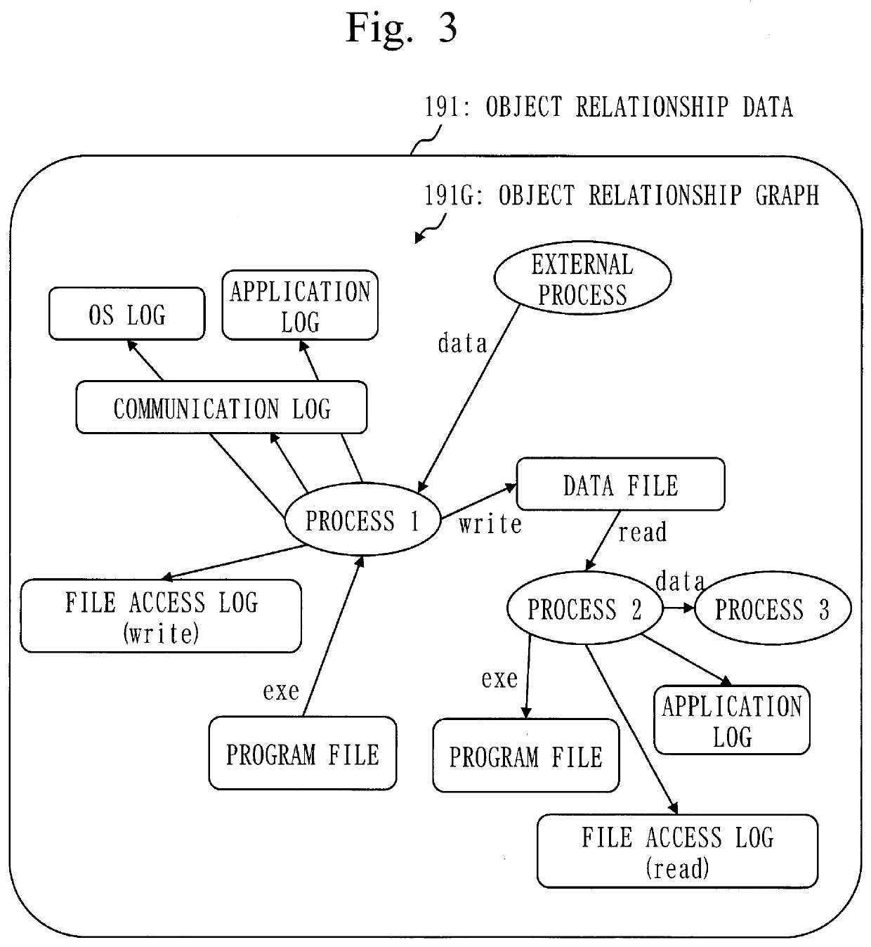
[0150]In step S113, the relationship building unit 120 adds an operation object node to the object relationship graph in a case where the operation object node is not in the object relationship graph. The relationship building unit 120 adds a target object node to the object relationship graph in a case where the target object node is not in the object relationship graph. Then, the relationship building unit 120 adds to the object relationship graph, an edge from the operation object node to the target object node. A relationship according to the operation type is appended to the edge.

example 2

[0151]In step S111, the reception unit 110 accepts log data that indicates Communication.

[0152]In step S112, the relationship building unit 120 extracts the operation type and the operation object information from the log data. The operation type is Communication. The operation object is a communication source process, and the target object is a communication destination process. In a case where each process of the communication source process and the communication destination process is the external process, each process is identified by an external address. The external address is an address that identifies an external device of the monitoring target.

[0153]In step S113, the relationship building unit 120 adds an operation object node to the object relationship graph in a case where the operation object node is not in the object relationship graph. The relationship building unit 120 adds a target object node to the object relationship graph in a case where the target object node is...


PUM


Abstract

A relationship building unit (120), based on a plurality of pieces of software operation data, each of which includes an operation type of software operation and operation object information that indicates a plurality of software objects used in the software operation, generates object relationship data that indicates a relationship between the plurality of software objects. A polluted range locating unit (130), based on the object relationship data and alert data that notifies occurrence of a cyberattack, generates polluted range data that indicates a polluted range affected by the cyberattack.

Description

CROSS REFERENCE TO RELATED APPLICATIONS[0001]This application is a Continuation of PCT International Application PCT / JP2020 / 012365, filed on Mar. 19, 2020, which is hereby expressly incorporated by reference into the present application.TECHNICAL FIELD[0002]The present disclosure relates to recurrence prevention of pollution caused by a cyberattack.BACKGROUND ART[0003]A measure such as the following is taken against a cyberattack.[0004]First, a cyberattack on a monitoring target is detected.[0005]Next, effects of the cyberattack are determined.[0006]Then, degraded operation of the monitoring target is decided on according to the effects of the cyberattack. For example, in the degraded operation, switching of functions or repositioning of functions is performed.[0007]Removal of a polluted part and action for recurrence prevention are necessary to be carried out for the effects of the cyberattack.[0008]The removal of the polluted part means deletion, restoration, initialization, and t...

Claims


Application Information

Patent Timeline
Patent Type & Authority Applications(United States)
IPC IPC(8): G06F21/56
CPCG06F21/566G06F2221/033G06F21/554
Inventor ATOBE, YUTA
Owner MITSUBISHI ELECTRIC CORP
Why Eureka
Try Eureka