
System and method for reducing search time and increasing search accuracy during interrogation of resonant devices

a technology of resonant devices and search accuracy, applied in the field of system and method of interrogating resonant devices, can solve the problems of no design that offers technology for reducing search time and accuracy levels, and achieves the effects of reducing search time, improving interrogation results, and searching more efficiently

Inactive Publication Date: 2007-08-02
MICHELIN RECH & TECH SA
View PDF7 Cites 0 Cited by
  • Summary
  • Abstract
  • Description
  • Claims
  • Application Information

AI Technical Summary

Benefits of technology

"The present invention provides an improved method for interrogating a resonant device by transmitting interrogation pulses at different frequencies and analyzing the received response levels to identify the frequency of resonance. The method offers advantages such as reduced search time, increased efficiency, and improved accuracy compared to known methods. The invention also provides features and steps for interrogating a resonant device using RF interrogation pulses of different bandwidths and frequencies within a given range of operation. The method can be used in various applications such as wireless search and interrogation."

Problems solved by technology

While various interrogation systems and corresponding search algorithms have been developed, no one design has emerged that offers technology for effecting SAW interrogation with reduced search time and accuracy levels as hereafter presented in accordance with the subject technology.

Method used


Image

  • System and method for reducing search time and increasing search accuracy during interrogation of resonant devices
  • System and method for reducing search time and increasing search accuracy during interrogation of resonant devices
  • System and method for reducing search time and increasing search accuracy during interrogation of resonant devices

Examples


Embodiment Construction

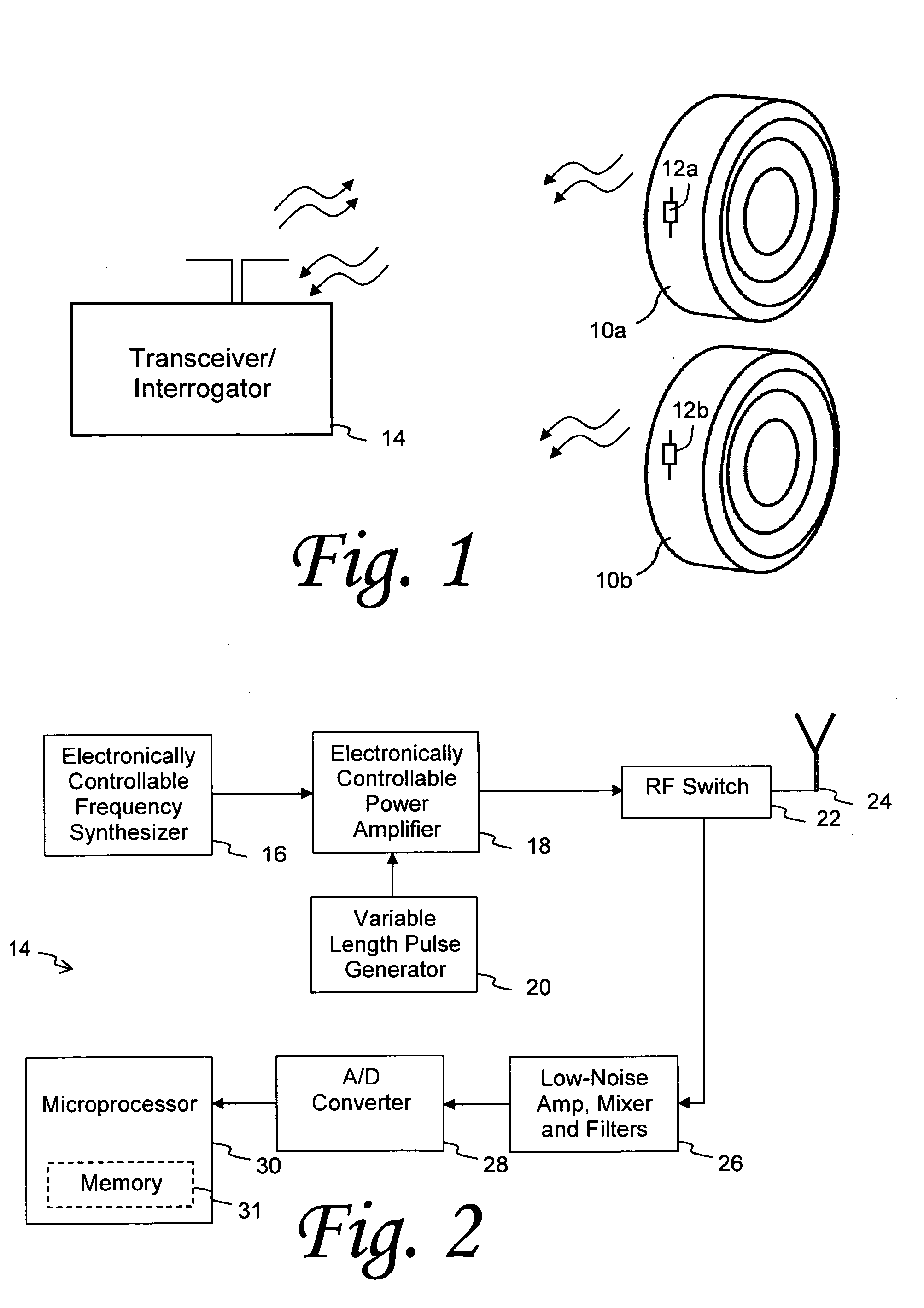
[0027] As discussed in the Summary of the Invention section, the present subject matter is particularly concerned with improved techniques for interrogating resonant devices, especially those available in condition-responsive devices such as surface acoustic wave (SAW) sensors. Such SAW sensors may be utilized in any environment where it is desired to monitor strain levels to which such sensors are subjected. A particular example of such an environment is within a vehicle tire or wheel assembly, where such physical characteristics as temperature and pressure may be monitored by one or more sensor devices. The remainder of this specification will describe aspects of the subject resonator interrogation techniques relative to a tire / wheel environment, although it should be appreciated that such techniques are not limited to utilization in such a particular application.

[0028] Referring now to FIG. 1, multiple tire structures 10a and 10b may respectively incorporate condition-responsive...


PUM


Abstract

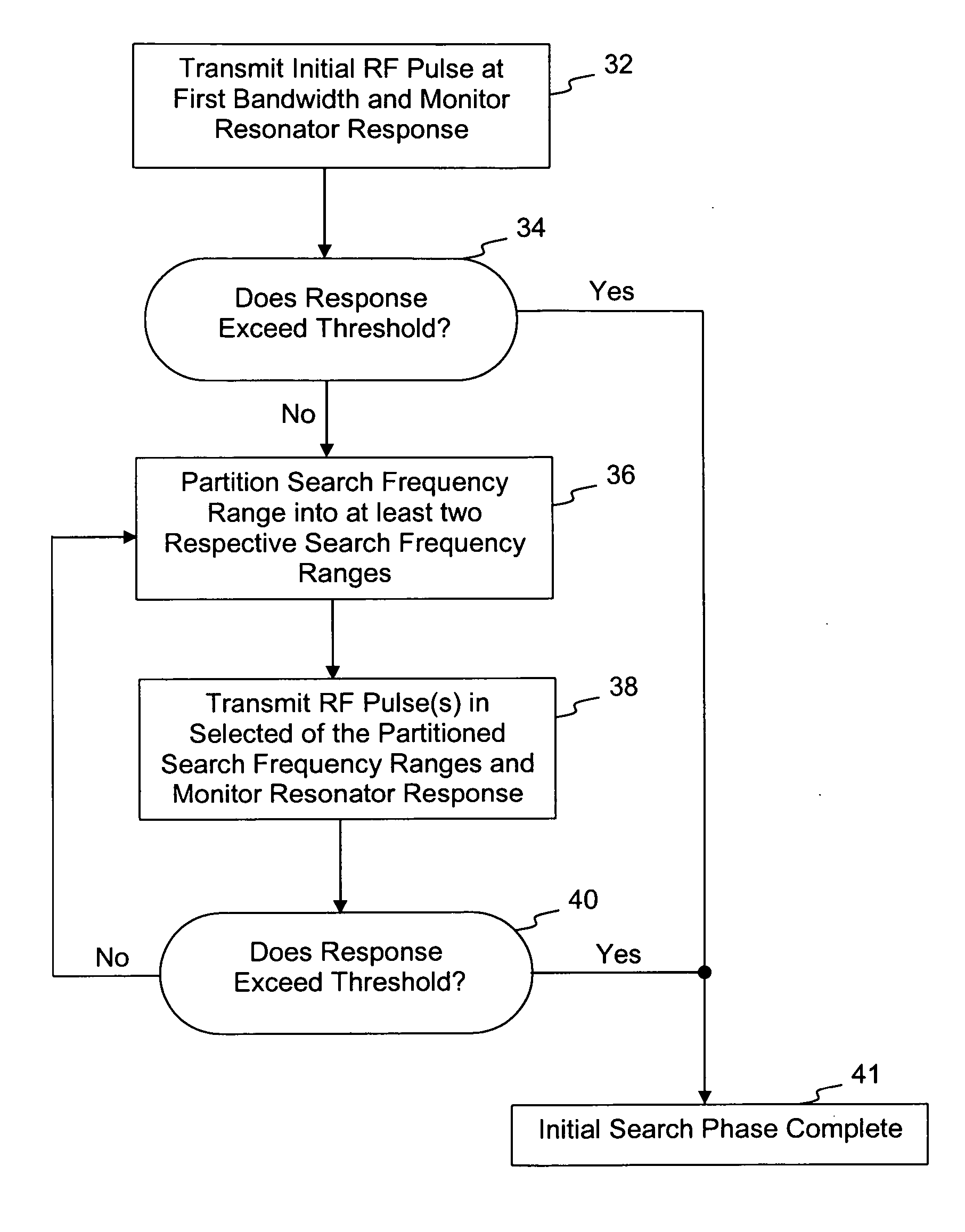
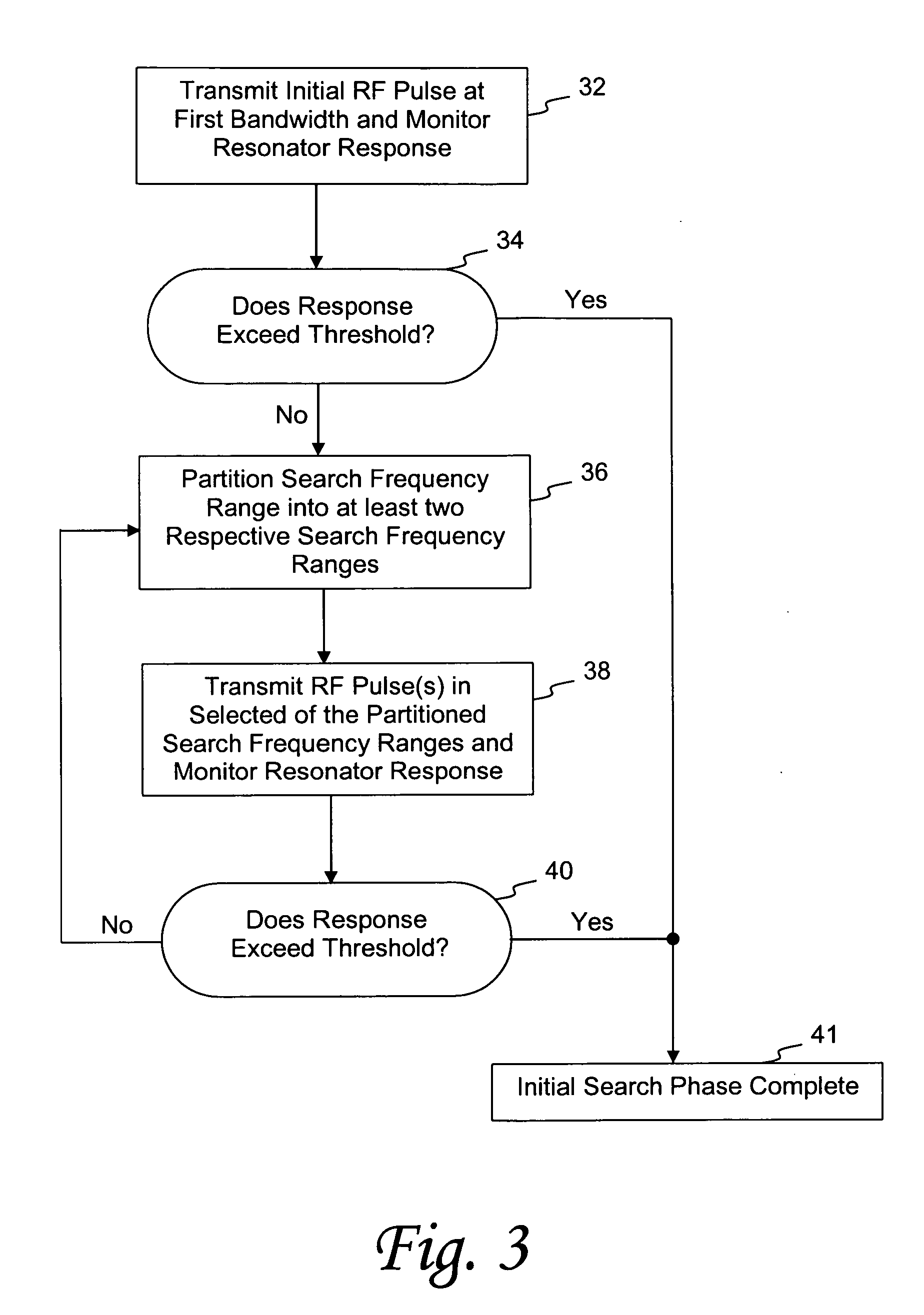
Methods for determining the resonant frequency for interrogation of a resonant device include steps for generating and transmitting RF interrogation pulses of various bandwidths to energize one or more SAW resonator elements. Initial RF interrogation pulses have a relatively wide bandwidth, such that the general location of a resonant device's resonant frequency can be expediently determined. Then, interrogation pulses having smaller bandwidth pulses can be transmitted near the determined general location of resonance to further narrow the location of resonance. In some emodiments, one or more initial interrogation pulses are transmitted in the center of or at an expected value within a range of operation of a resonant device. If the resonant frequency is not located at this initial location, then the range of operation is divided into halves (or other number of generally equal frequency range segments) and one or more interrogation pulses are transmitted at the center of each of the new search frequency range segments. This process of partitioning the search frequency range continues until the resonant frequency is located.

Description

FIELD OF THE INVENTION [0001] The present invention generally concerns a system and method of interrogating resonator elements such as those present in surface acoustic wave (SAW) devices. Such SAW devices may be incorporated in a tire or wheel assembly for sensing such physical parameters as ambient temperature and pressure. The subject interrogation technologies are generally characterized by reduced search time and increased search accuracy than other known methods. BACKGROUND OF THE INVENTION [0002] The incorporation of electronic devices with tire structures yields many practical advantages. Tire electronics may include sensors and other components for relaying tire identification parameters and also for obtaining information regarding various physical parameters of a tire, such as temperature, pressure, number of tire revolutions, vehicle speed, etc. Such performance information may become useful in tire monitoring and warning systems, and may even potentially be employed with...

Claims


Application Information

Patent Timeline
Patent Type & Authority Applications(United States)
IPC IPC(8): B60C23/00H04B5/48
CPCB60C23/0408
Inventor THIESEN, JACKO'BRIEN, GEORGE P.
Owner MICHELIN RECH & TECH SA
Learn More