
Multiple module computer system and method

a computer system and multi-module technology, applied in the field of computing devices, can solve the problems of poor display technology of computing devices, poor viewing characteristics of small flat panel displays, and many limitations of laptop computers, and achieve the effects of improving processing and maintenance features, improving cpu performance, and being convenient and efficien

Inactive Publication Date: 2005-08-18
ACQIS LLC
View PDF99 Cites 28 Cited by
  • Summary
  • Abstract
  • Description
  • Claims
  • Application Information

AI Technical Summary

Benefits of technology

"The present invention provides a system with multiple computer modules that can independently operate to provide backup capability, dual processing, and increased CPU performance. The computer modules have a connector that can be housed in an enclosure, and each module has its own processing unit, main memory, graphics controller, and mass storage device. The computer modules can be coupled to a console with a connector, and the console can have a video switch circuit for switching between video signals from each module. The invention also provides a method of using multiple computer modules, including a method of interfacing two PCI or PCI-like buses using a non-PCI or non-PCI-like channel. This allows for the use of LVDS channels, which are faster, more cable-friendly, and consume less power than PCI bus channels. The invention also provides an apparatus for bridging two computer interface buses in a microprocessor based computer system."

Problems solved by technology

Although somewhat successful, laptop computers have many limitations.
These computing devices have poor display technology.
In fact, these devices often have a smaller flat panel display that has poor viewing characteristics.
Additionally, these devices also have poor input devices such as smaller keyboards and the like.
Furthermore, these devices have limited common platforms to transfer information to and from these devices and other devices such as PCs.
Up to now, there has been little common ground between these platforms including the PCs and laptops in terms of upgrading, ease-of-use, cost, performance, and the like.
A drawback to having two separate computers is that the user must often purchase both the desktop and laptop to have “total” computing power, where the desktop serves as a “regular” computer and the laptop serves as a “portable” computer.
Purchasing both computers is often costly and runs “thousands” of dollars.
The user also wastes a significant amount of time transferring software and data between the two types of computers.
Another drawback with the current model of separate portable and desktop computer is that the user has to spend money to buy components and peripherals the are duplicated in at least one of these computers.
Because program software and supporting programs generally must be installed upon both hard drives in order for the user to operate programs on the road and in the office, hard disk space is often wasted.
However, dual CPU systems may suffer limited performance improvement if memory or disk drive bandwidth becomes the limiting factor.
In running multiple applications, memory and disk drive data throughput will become the limiting factor in improving performance with multi-processor systems.
However, the interface is limited in a number of ways.
Consequently, the interface is subject to the limitations under which PCI buses operate.
One such limitation is the fact that PCI buses are not cable friendly.
One disadvantage of an interface having a relatively large number of conductive lines and pins is that it costs more than one that uses a fewer number of conductive lines and pins.
Additionally, an interface having a large number of conductive lines is bulkier and more cumbersome to handle.
Finally, a relatively large number of signal channels in the interface renders the option of using differential voltage signals less viable because a differential voltage signal method would require duplicating a large number of signal lines.

Method used


Image

  • Multiple module computer system and method
  • Multiple module computer system and method
  • Multiple module computer system and method

Examples


Embodiment Construction

[0046] According to the present invention, a technique including a method and device for multi-module computing is provided. In an exemplary embodiment, the present invention provides a system including a plurality of computer modules that can independently operate to provide backup capability, dual processing, and the like.

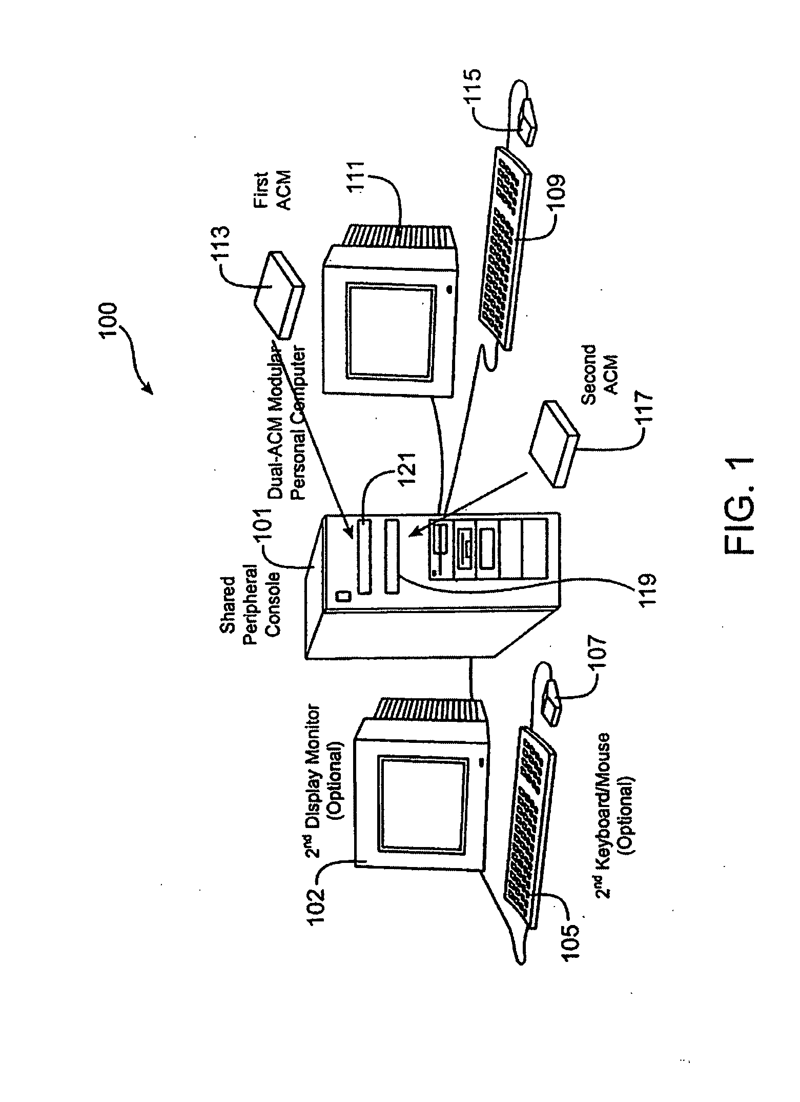
[0047]FIG. 1 is a simplified diagram of a computer system 100 according to an embodiment of the present invention. This diagram is merely an illustration and should not limit the scope of the claims herein. One of ordinary skill in the art would recognize other variations, modifications, and alternatives. The computer system 100 includes an attached computer module (i.e., ACM) 113, a desktop console 101, among other elements. The computer system also has another ACM module 117. Each ACM module has a respective slot 121, 119, which mechanically houses and electrically couples each ACM to the computer console. Also shown is a display 111, which connects to the con...


PUM


Abstract

A computer system for multi-processing purposes. The computer system has a console comprising a first coupling site and a second coupling site. Each coupling site comprises a connector. The console is an enclosure that is capable of housing each coupling site. The system also has a plurality of computer modules, where each of the computer modules is coupled to a connector. Each of the computer modules has a processing unit, a main memory coupled to the processing unit, a graphics controller coupled to the processing unit, and a mass storage device coupled to the processing unit. Each of the computer modules is substantially similar in design to each other to provide independent processing of each of the computer modules in the computer system.

Description

CROSS REFERENCE TO RELATED APPLICATIONS [0001] The present application claims priority as a continuation of U.S. nonprovisional patent application Ser. No. 10 / 772,214, filed Feb. 3, 2004, which is a continuation of U.S. nonprovisional patent application Ser. No. 09 / 569,758, filed May 12, 2000 (Now U.S. Pat. No. 6,718,415), which claimed priority to U.S. Provisional Application No. 60 / 134,122 filed May 14, 1999, commonly assigned, and hereby incorporated by reference.BACKGROUND OF THE INVENTION [0002] The present invention relates to computing devices. More particularly, the present invention provides a system including a plurality of computer modules that can independently operate to provide backup capability, dual processing, and the like. Merely by way of example, the present invention is applied to a modular computing environment for desk top computers, but it will be recognized that the invention has a much wider range of applicability. It can be applied to a server as well as o...

Claims


Application Information

Patent Timeline
Patent Type & Authority Applications(United States)
IPC IPC(8): G06F1/12
CPCG06F1/12G06F13/385G06F13/4068G06F13/4282G06F1/08G06F13/4221G06F13/42G06F13/102G06F13/20G06F13/4027G06F13/409Y02D10/00G06F1/1632
Inventor CHU, WILLIAM W.Y.
Owner ACQIS LLC
Learn More