Near-field communication surface and method for locating on said surface

a communication surface and near-field technology, applied in the direction of sensing by electromagnetic radiation, using reradiation, instruments, etc., can solve the problems of large disturbance in electromagnetic field, affecting the accuracy of locating, and not being able to precisely identify objects associated with said devices,

Pending Publication Date: 2022-09-15
CENTILOC
View PDF4 Cites 0 Cited by
  • Summary
  • Abstract
  • Description
  • Claims
  • Application Information

AI Technical Summary

Problems solved by technology

As soon as an antitheft device is placed in the field produced by the electromagnetic terminals, said device begins to resonate and creates significant disturbance in the electromagnetic field.
However, a tracking method of this kind does not make it possible to exactly identify an object associated with said device.
Furthermore, the number of readers is proportional to the number of antennas, which is relatively expensive.
A method of this kind is relatively complex to develop, and can thus prove to be fairly expensive if a high degree of locati

Method used


Image

  • Near-field communication surface and method for locating on said surface
  • Near-field communication surface and method for locating on said surface
  • Near-field communication surface and method for locating on said surface

Examples


Embodiment Construction

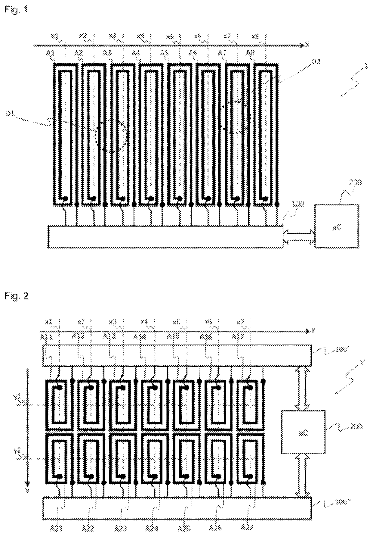
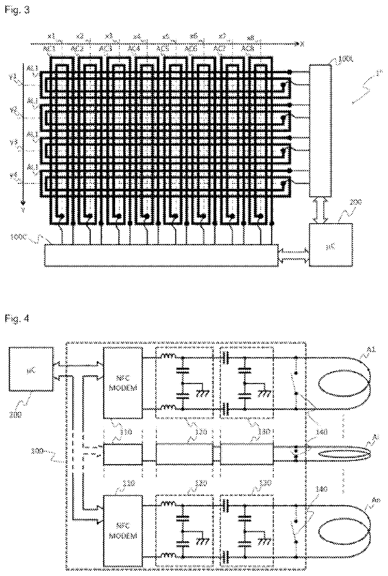
[0042]By “near field communication,” the present document refers to NFC technology that is limited to a few centimeters, and uses antennas implemented by means of conductive loops forming half-transformers both on the reader side and on the electronic tag side. The communication thus implemented is achieved by means of a magnetic field which couples the transmission antenna of the reader and the antenna for recovering energy from an electronic tag.

[0043]By “electronic tag,” the present document refers to an identification device comprising an electronic chip coupled to an antenna which forms a coil and powers itself by means of the magnetic field created by the reader. An identification device of this kind is generally in the form of a tag which can be easily fixed on a number of types of packaging or products. Nonetheless, the invention is not limited to a form factor of the “tag” type, and may for example be in the form of a grain of rice or any other form of electronic device.

[00...


PUM


Abstract

The invention relates to a near-field communication surface intended to communicate with at least one electronic tag. The surface comprises a plurality of antennas, each antenna having a position along an axis, a circuit for reading electronic tags that is connected to said antennas in order to supply them with power and communicate with said electronic tag, and a processing unit controlling the antennas and the circuit for reading electronic tags. The processing unit is configured to activate just one antenna at a time and the reading circuit in order to communicate with said at least one electronic tag, and to locate a position of the electronic tag along the axis according to a number of responses or to a response time from the electronic tag. The invention also relates to the locating method.

Description

TECHNICAL FIELD[0001]The present invention relates to a near-field communication surface and to a method for locating on said surface. The invention makes it possible to locate, on a near-field communication surface, one or more electronic ID tags or devices placed on said surface.TECHNOLOGICAL BACKGROUND[0002]Automatic tracking of an object in a given zone can be achieved in various ways. Regarding electronic antitheft, it is known to position electromagnetic terminals at store exits, and to fit products with an antitheft device comprising a resonant circuit that is tuned to the frequency of the electromagnetic field of said terminals. As soon as an antitheft device is placed in the field produced by the electromagnetic terminals, said device begins to resonate and creates significant disturbance in the electromagnetic field. This disturbance has been found to be easily detectable, and makes it possible to locate an antitheft device present in a specified zone. However, a tracking ...

Claims


Application Information

Patent Timeline
IPC IPC(8): G06K7/10
CPCG06K7/10297G06K7/10316G01S5/02H01Q1/2216H01Q21/00G06K7/10099H04B5/0056G01S13/75G01S13/878
Inventor PALMADE, ROMAINHENNINOT, LOÏCBONNIN, FRÉDÉRICK
Owner CENTILOC
Why Eureka
Try Eureka