
Locking arrangement for a parking brake

a technology for locking arrangements and parking brakes, which is applied in the direction of mechanical control devices, controlling members, limiting/preventing/returning parts movement, etc., can solve the problems of required play and no longer secured parking brakes

Active Publication Date: 2011-10-06
EDSCHA ENG GMBH
View PDF2 Cites 0 Cited by
  • Summary
  • Abstract
  • Description
  • Claims
  • Application Information

AI Technical Summary

Benefits of technology

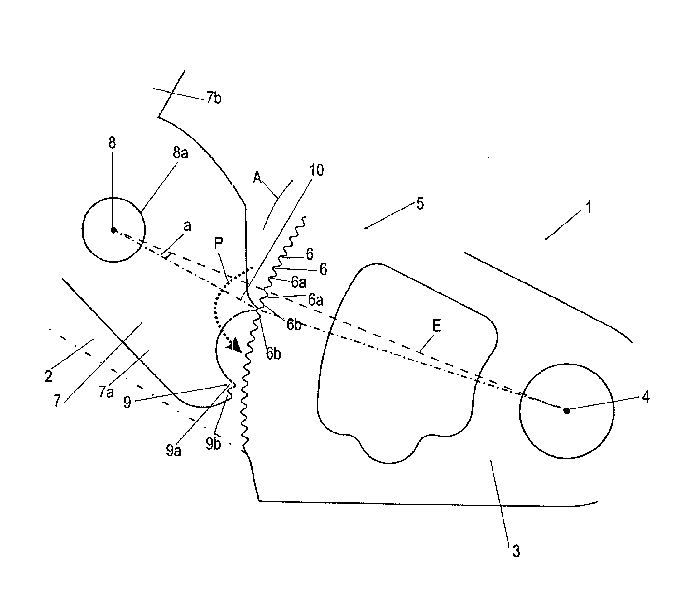
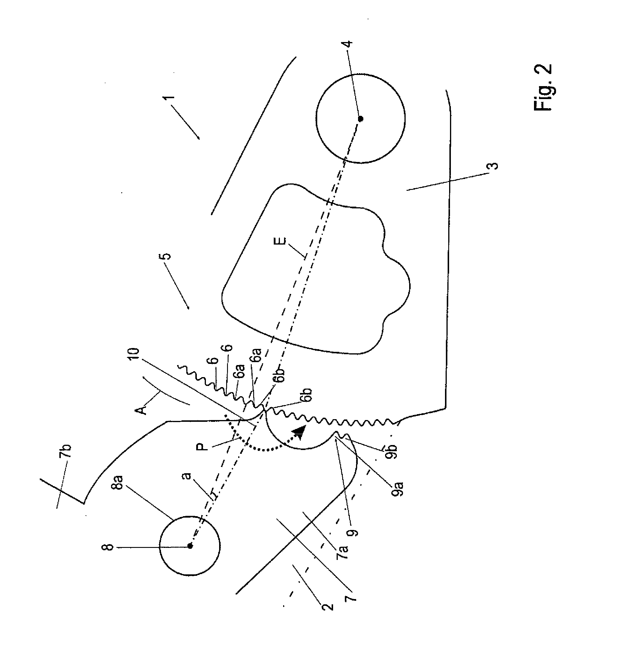
[0011]The auxiliary nose assigned to the catch is preferably disposed on the catch itself, with either pivotable arrangement by way of a connecting joint or integral formation with the catch being possible. The integral configuration, in particular, has the advantage that, by virtue of the known distance with respect to the engaging nose, reliable engagement kinematics can be achieved, a specific bearing location is not required and the catch is simple to manufacture.
[0023]It is expedient if the catch is biased in the direction of engagement by a spring unit, it being possible at the same time for the spring unit to bias the release device counter to the actuating direction thereof. The release device can then advantageously pivot the catch out of engagement against the bias of the spring unit, which excludes accidental actuation.

Problems solved by technology

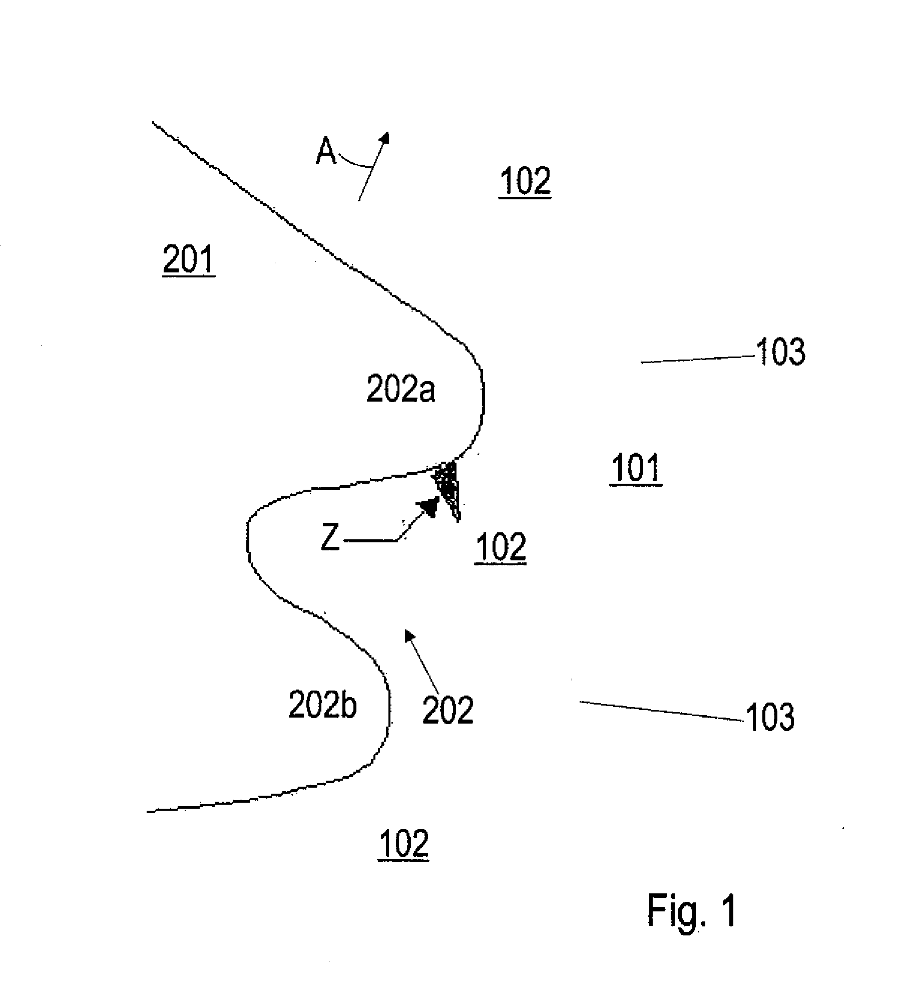
In known locking arrangements, there is a problem that, at certain lowering angles, an engaging nose shaped in the form of a tooth comes into contact with a tooth of the tooth system in such a way that the static friction is sufficient to achieve metastable retention of the catch provided with the engaging nose, but this is still not a positive-locking position of engagement between two tooth flanks of the tooth system.
This metastable position, which is also referred to as “half locking”, may be overcome in the event of shocks or the like, with the possible result that the engaging nose enters the depression between two adjacent tooth flanks and reaches a stable locking position, there is, however, a risk that instead the engaging nose slides off and, under the tension of the brake cable, slides into the lowered brake position with the brake actuating lever, the result being that the parking brake is no longer secured.
The disadvantage with the known locking arrangement is, on the one hand, the required play in the pivot of the catch, this being necessary in order initially to insert just one, first tooth.
Owing to the equidistant tooth intervals, there is furthermore the risk that all the tooth tips of the teeth of the engaging nose will come into contact outside the recesses of the tooth system, thereby allowing the catch to slide off.

Method used


Image

  • Locking arrangement for a parking brake
  • Locking arrangement for a parking brake
  • Locking arrangement for a parking brake

Examples


Embodiment Construction

[0030]FIG. 1 illustrates the case where “half-locking” occurs, in which the engaging nose of a locking catch adopts only a metastable position in relation to a tooth system and there is a risk that it will slide off as a result of a shock. The tooth system 101 has a plurality of teeth 102 and has a profile of the approximately circular segment type, a tooth recess 103 being provided between adjacent teeth 102. When the parking brake is applied, a catch 201 is pivoted in the direction of arrow A until the brake actuating lever is lowered. In the illustrative embodiment shown, the catch 201 has an engaging nose 202 designed as a double tooth, with an upper tooth 202a and a lower tooth 202b. In order to achieve reliable locking, it is expected that the teeth 202a, 202b of the engaging nose 202 will enter the respective recesses 103 between adjacent teeth 102 of the tooth system 101. The parking brake is then reliably locked. In the contact position illustrated in FIG. 1, in which the t...


PUM


Abstract

A locking arrangement for locking a brake part held under tension is provided. The locking arrangement includes a gearing having a plurality of adjoining gears, a catch which can be pivoted about a catch coupling and which has at least one engaging nose that is biased in the direction toward the gearing on one engagement end. Either the catch coupling or the gearing can be pivoted about a main axis relative to each other, and a parking brake equipped with the locking arrangement. A locking arrangement, or a parking brake enabling an improved locking is created in that an auxiliary nose is associated with the catch at a distance from the engaging nose, and that the auxiliary nose is disposed such that it may be brought into contact with the gearing in front of the engaging nose.

Description

[0001]This application claims the benefit of German Patent Application DE 10 2008 049 333.3 filed Sep. 29, 2008 and German Patent Application DE 10 2008 056 752.3 filed Nov. 11, 2008, both of which are hereby incorporate by reference herein.[0002]The invention relates to a locking arrangement for a parking brake for locking a brake part held under tension.BACKGROUND[0003]Locking arrangements for locking brake parts held under tension are known in practice and, in said locking arrangements, a first brake part has a tooth system, into which a catch provided on a second brake part engages by means of an engaging nose and thereby secures the two parts relative to one another in terms of rotary motion. By way of example, a locking arrangement of this kind is provided for locking the brake actuating lever on a lever holder or for locking a brake cable adjustment device when the brake actuating lever is raised and the free movement of the adjustment device is supposed to be blocked.[0004]I...

Claims


Application Information

Patent Timeline
Patent Type & Authority Applications(United States)
IPC IPC(8): B60T7/10B60T7/08
CPCB60T7/104Y10T74/20684B60T11/04B60T7/045Y10T74/20612
Inventor GUTIERREZ FERNANDEZ, JOSE MANUEL
Owner EDSCHA ENG GMBH
Learn More