Diagnostic and control method for a vehicle system

a vehicle system and diagnostic strategy technology, applied in the direction of program control, testing/monitoring control system, instruments, etc., can solve the problems of unintended behavior, unintended behavior, unwanted changes in vehicle acceleration, etc., to reduce the chance of unwanted vehicle deceleration, reduce the chance of unintended vehicle deceleration, and operate the clutch effectively and efficiently

Active Publication Date: 2022-11-17
DANA BELGIUM
View PDF5 Cites 0 Cited by
  • Summary
  • Abstract
  • Description
  • Claims
  • Application Information

AI Technical Summary

Benefits of technology

[0006]To overcome at least a portion of the aforementioned drawbacks, a method for operation of a vehicle system is provided. In one example, the method includes determining, at a diagnostic controller or processing unit, a vehicle speed from a vehicle speed sensor and a position of a plurality of clutches in a transmission of the vehicle system. The method further includes identifying an unauthorized clutch position based on the clutch positions and the vehicle speed. The method even further includes, in response to identification of the unauthorized clutch position, operating the plurality of clutches in a fault state. In one example, the fault state or mode may be realized by removing either all or most of the torque applied at vehicle wheels by removing the closing force of the clutches, bringing them into an opened state. Therefore, the system can effectively and efficiently identify a clutch fault and operate the clutches to reduce the chance of unwanted vehicle deceleration. Consequently, the operator's experience is enhanced. Further, by executing the diagnostics and driveline control on separate controllers or processing units increases the system's adaptability.
[0007]In one example, the unauthorized clutch position may be identified by comparing the vehicle speed and the clutch position against a lookup truth table. Rows of the lookup truth table are populated with lower and upper speed thresholds that correspond to a plurality of unauthorized clutch position settings. In this way, the clutches may be diagnosed using an efficient and reliable routine that has higher diagnostic confidence than strategies which compare actual and intended clutch settings, thus guarding against both undesired clutch conditions which may lead to unwanted changes in vehicle kinematic performance (e.g., unintended vehicle deceleration) and unwarranted triggering of the fault state that may hamper vehicle performance.

Problems solved by technology

Different sets of vehicle driveline conditions may lead to unintended behaviors.
The unintended behaviors may include unwanted changes in vehicle acceleration and other undesirable kinematic behavior.
For instance, a number of conditions can cause erroneous clutch settings that may lead to unwanted vehicle braking or movement in an unintended direction.
For instance, fault detection strategies which rely on comparison of actual vs. intended gear ratio are processing intensive strategies that may lead to the incorrect identification of a fault, in certain situations.
This superfluous fault detection may restrict vehicle performance and lead to unnecessary servicing of the vehicle, in some cases.
This may involve complex processing strategies that are not always effective or reliable, due to the fault misdiagnoses, described above.
Additionally, using a single controller for both diagnostic and control operations may prove to be inflexible and inefficient with regard to altering or updating routines of either operation.
Further, other prior fault detection strategies have involved complex systems that use a comparatively large number of inputs and guard against a large number of unwanted settings such as software faults, hydraulic faults, etc.
As such, previous diagnostic strategies may demand a large amount of processing resources to implement, and therefore may decrease the system's processing efficiency.

Method used


Image

  • Diagnostic and control method for a vehicle system
  • Diagnostic and control method for a vehicle system
  • Diagnostic and control method for a vehicle system

Examples


Embodiment Construction

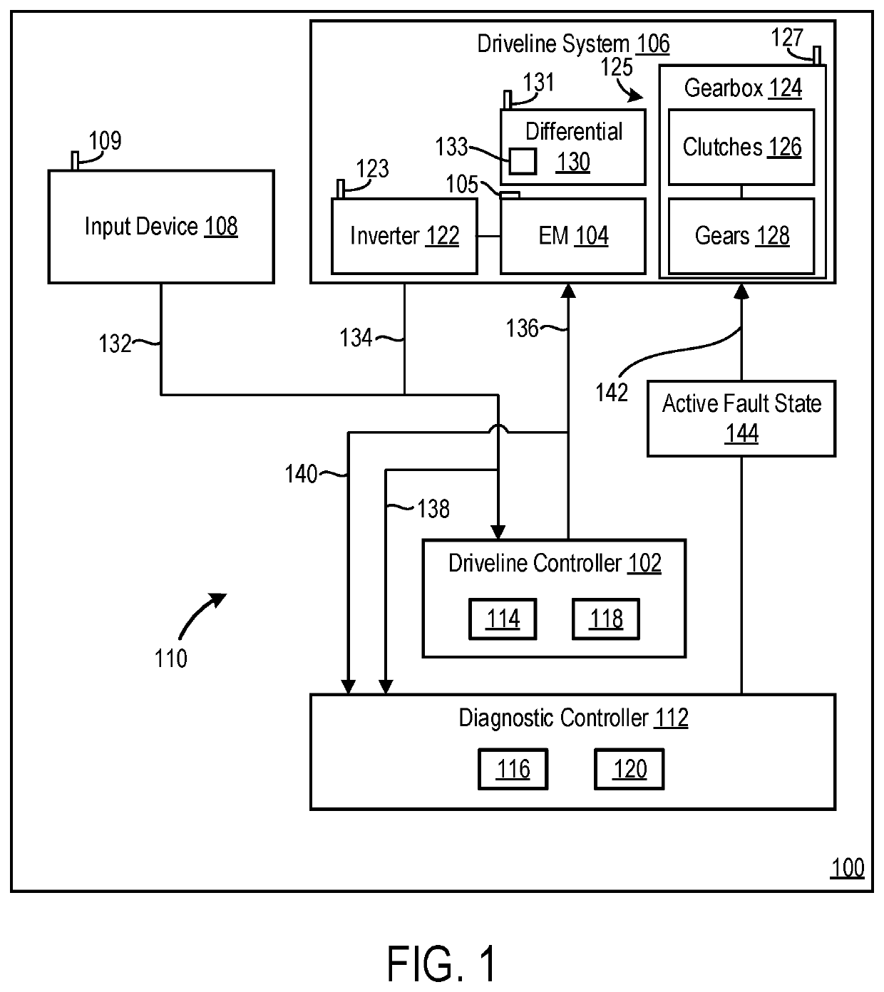
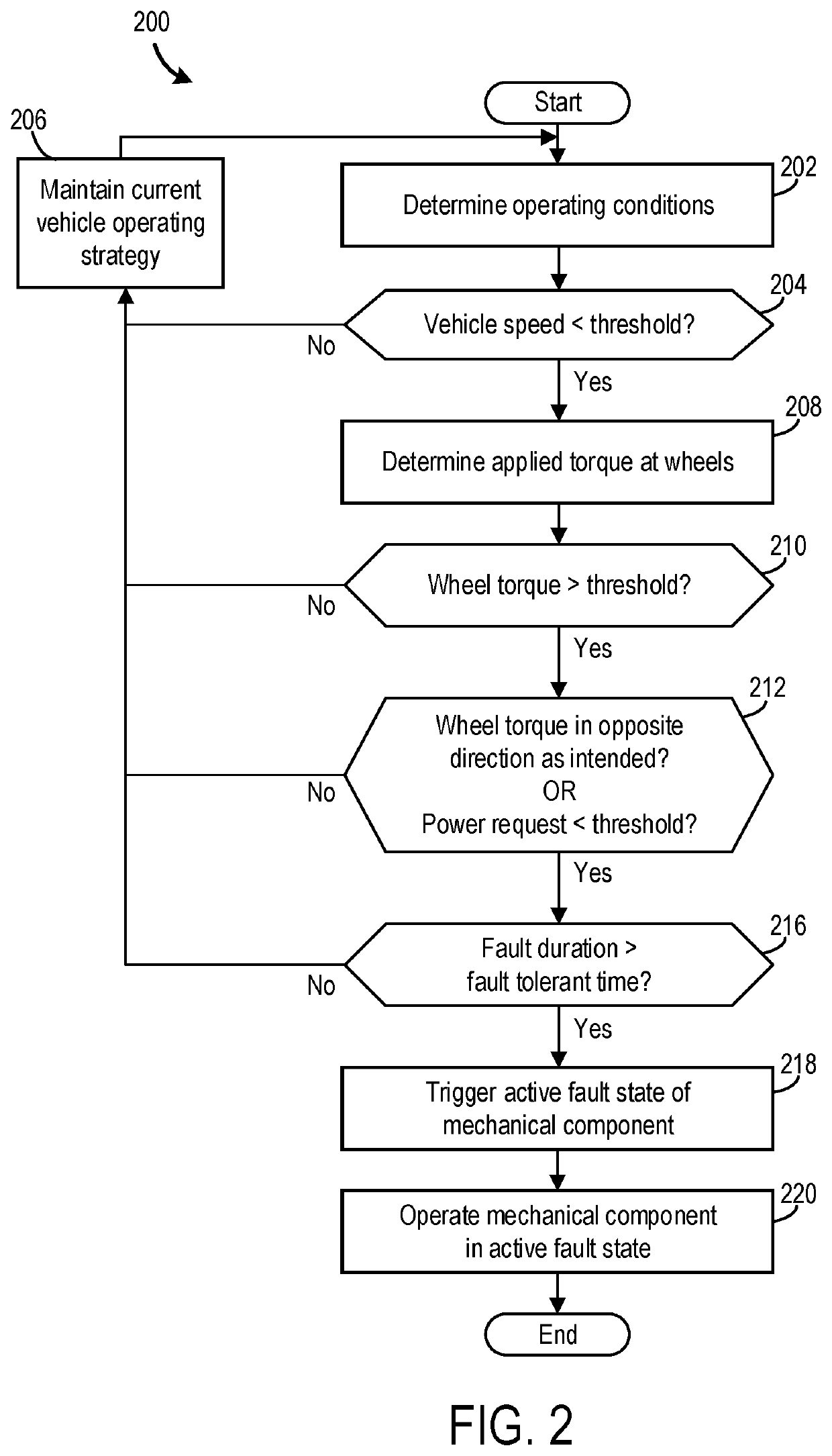
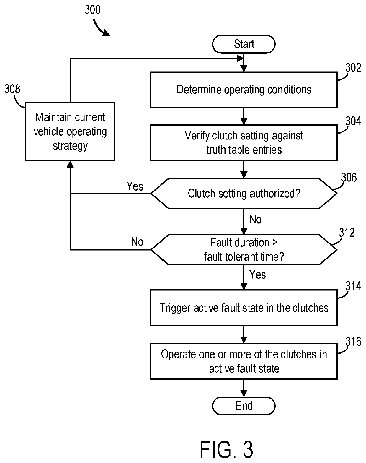
[0016]The following description relates to a driveline component control strategies and fault diagnostics in a vehicle system. The system uses efficient logic for confident and independent fault diagnosis to reduce the likelihood of undesired driveline and more generally vehicle behaviors. The system uses independent controllers, or processing units, to implement nominal driveline control strategies and diagnostic (e.g., fault detection) strategies. As such, diagnostic routines may be executed independently from nominal control strategies and is not influenced by the nominal control strategies. Thus, a diagnostic controller determines a fault condition of a driveline component and triggers a fault state to operate the driveline component in a fault mode, overriding the nominal control settings of a driveline controller. The separation of control and diagnostic logic allows for independent alteration of control and fault applications, providing increased system adaptability and diagn...


PUM


Abstract

Methods and systems are provided for controlling and diagnosing a mechanical vehicle component. In one example, a method may include determining a vehicle speed and a plurality of clutch position settings at a diagnostic controller, and identifying unauthorized conditions based on these determinations. Further, the diagnostic controller may trigger an active fault state of the mechanical vehicle component in order to avoid unauthorized conditions that may lead to unwanted or unanticipated changes in vehicle motion.

Description

TECHNICAL FIELD[0001]The present description relates generally to control and diagnostic strategies in a vehicle system. More particularly, the present description relates to techniques for fault monitoring in a driveline system.BACKGROUND AND SUMMARY[0002]Different sets of vehicle driveline conditions may lead to unintended behaviors. The unintended behaviors may include unwanted changes in vehicle acceleration and other undesirable kinematic behavior. For instance, a number of conditions can cause erroneous clutch settings that may lead to unwanted vehicle braking or movement in an unintended direction. In an attempt to avoid these unwanted behaviors, previous vehicle control and diagnostic systems have guarded against unintended behaviors by verifying actual settings against requested settings. When the mismatch in the settings is too large, actions are taken to discontinue or altogether avoid the unintended behaviors.[0003]U.S. Pat. No. 7,980,981 B2 to Kawaguchi et al. discloses...

Claims


Application Information

Patent Timeline
Patent Type & Authority Applications(United States)
IPC IPC(8): B60W20/30B60W10/02B60W10/11B60W30/18B60W30/19
CPCB60W20/30B60W10/0235B60W10/11B60W10/026B60W30/18172B60W30/19B60W10/06G05B23/0213G05B2219/24065F16H61/12F16H2061/1212F16H2061/1248F16H59/44F16H59/70B60W2520/10B60W10/08B60W2520/30B60W10/02B60W2510/0208B60W2510/10B60W2540/10B60W2540/103B60W2710/08B60W2710/10B60W20/50
Inventor DECKMYN, PETERAELVOET, BJORNFEVERY, BRECHT
Owner DANA BELGIUM
Why Eureka
Try Eureka