Wing tip device

a technology of wing tip and wing, which is applied in the direction of airflow influencers, heat reducing structures, transportation and packaging, etc., can solve the problems of excessive boundary layer growth, increased drag, interference effect between fuselage and wings of aircraft,

Active Publication Date: 2022-11-17
AIRBUS OPERATIONS LTD
View PDF6 Cites 0 Cited by
  • Summary
  • Abstract
  • Description
  • Claims
  • Application Information

AI Technical Summary

Benefits of technology

[0007]A fairing is an external structure added to smooth the outline between respective surfaces, increase aerodynamic streamlining, and reduce drag.
[0009]By placing the fairing between the first and second wing tip device elements, the interference effects and vortical flow in the junction between the wing tip device elements can be reduced, thereby reducing drag, especially at high speed. Extending the fairing to project aft from the trailing edge of the second wing tip device element mitigates the adverse pressure gradients so that boundary layer growth and drag are both reduced.
[0018]The fairing may extend forward of the second wing tip device element trailing edge. The presence of a horseshoe vortex in the junction adjacent the leading edge of the second wing tip device element can be exacerbated further aft. By providing a fairing adjacent to and forward of the leading edge of the second wing tip device element, these effects can be reduced and the associated increases in drag mitigated.

Problems solved by technology

For example, interference effects exist between an aircraft's fuselage and its wings.
These effects can be particularly pronounced on wing tip devices with multiple lifting surfaces, such as split winglets, due to both surfaces generating lift and the sharp intersection of a downlet having horseshoe vortex interference effects.
At the rearward junction of these lifting elements, adverse pressure gradients are present from the two lifting surfaces, the combination of which can cause excessive boundary layer growth and increased drag.

Method used


Image

  • Wing tip device
  • Wing tip device
  • Wing tip device

Examples


Embodiment Construction

)

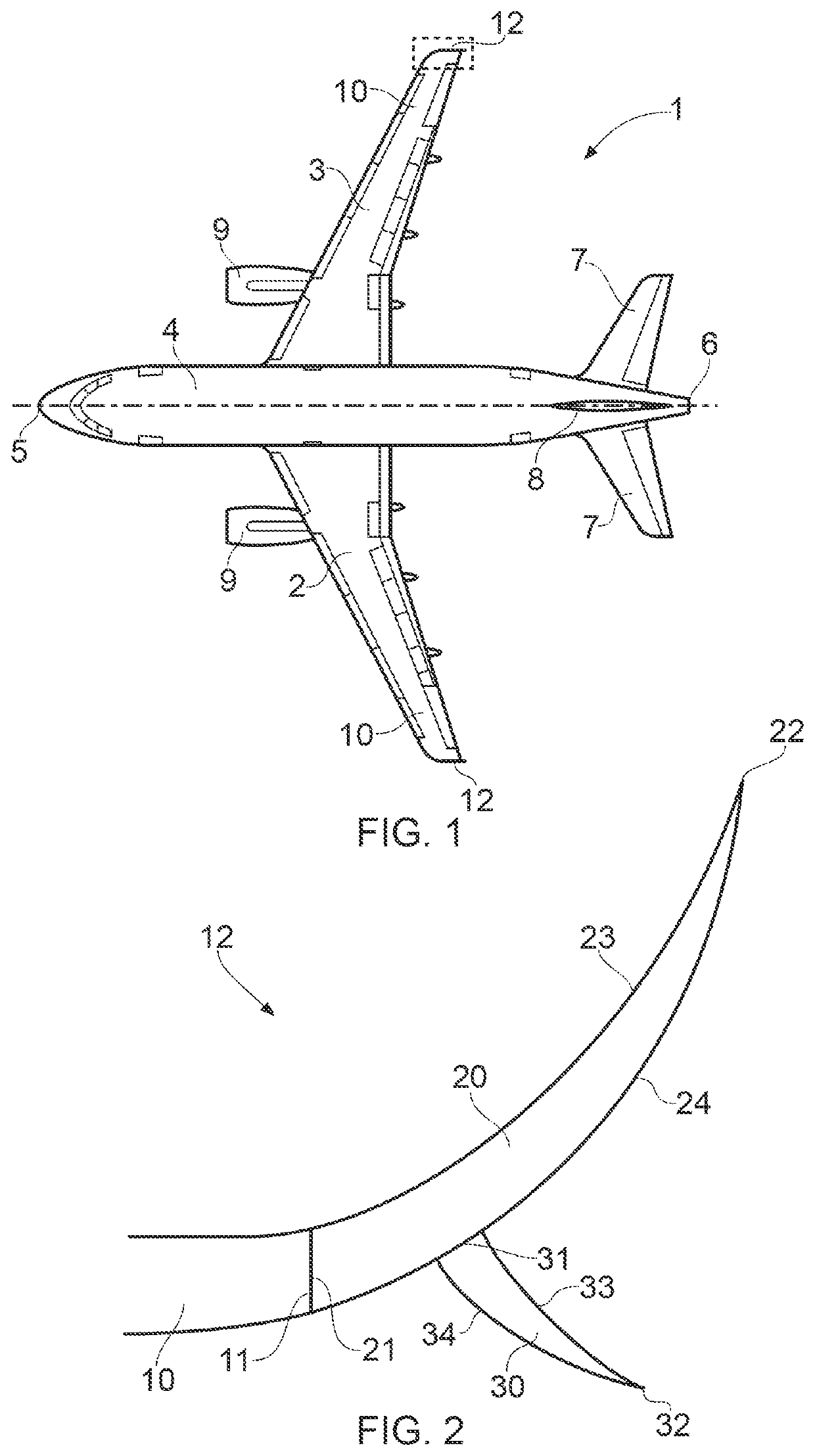
[0050]FIG. 1 shows an existing aircraft 1 with port and starboard fixed wings 2, 3, engines 9, a fuselage 4 with a nose end 5 and a tail end 6, the tail end 6 including horizontal and vertical stabilising surfaces 7, 8. The aircraft 1 is a typical jet passenger transonic transport aircraft but the invention is applicable to a wide variety of fixed wing aircraft types, including commercial, military, passenger, cargo, jet, propeller, general aviation, etc. with any number of engines attached to the wings or fuselage.

[0051]Each wing 2, 3 of the aircraft 1 has a cantilevered structure with a length extending in a span-wise direction from a root to a tip, the root being joined to the aircraft fuselage 4. At the tip of each wing 2, 3 is a wing tip device 12 outboard of a main wing portion 10. The wings 2, 3 are aft swept and have a number of flight control surfaces.

[0052]As the wings 2, 3 are similar in construction, only the wing tip device 12 of the starboard wing 3 will be described ...


PUM


Abstract

A wing tip device having a first wing tip device element for attaching at a first wing tip device element root to a tip of an aircraft wing, and a second wing tip device element extending from a second wing tip device element root to a second wing tip device element tip, the second wing tip device element root outboard, when viewed in the wing planform direction, of the first wing tip device element root; the first wing tip device element having a first wing tip device element leading edge and a first wing tip device element trailing edge, and the second wing tip device element having a second wing tip device element leading edge and a second wing tip device element trailing edge; and a fairing between the first and second wing tip device element which extends aft from the second wing tip device element trailing edge.

Description

RELATED APPLICATION[0001]This application is a divisional application to U.S. Ser. No. 16 / 574,461, filed Sep. 18, 2019, which claims priority to United Kingdom GB Application Number GB 1815357.7 filed Sep. 20, 2018, the entirety of which applications are incorporated by reference.FIELD OF THE INVENTION[0002]The present invention relates to a wing tip device, a wing including the wing tip device, an aircraft including the wing, and a method of attaching a wing tip device.BACKGROUND OF THE INVENTION[0003]Interference effects between two objects in an airflow can be created when the wetted surfaces of those objects are in close proximity. For example, interference effects exist between an aircraft's fuselage and its wings. These effects can be particularly pronounced on wing tip devices with multiple lifting surfaces, such as split winglets, due to both surfaces generating lift and the sharp intersection of a downlet having horseshoe vortex interference effects.[0004]At the rearward ju...

Claims


Application Information

Patent Timeline
Patent Type & Authority Applications(United States)
IPC IPC(8): B64C23/06B64C7/00
CPCB64C23/069B64C7/00B64C3/36B64C1/26Y02T50/10B64C3/58B64C5/08
Inventor COMMIS, BENWRIGHT, CHRISTOPHER
Owner AIRBUS OPERATIONS LTD
Why Eureka
Try Eureka