Battery cell for testing internal short circuit, and method for testing internal short circuit of battery cell by using same

Pending Publication Date: 2022-11-17
LG ENERGY SOLUTION LTD
View PDF0 Cites 0 Cited by
  • Summary
  • Abstract
  • Description
  • Claims
  • Application Information

AI Technical Summary

Benefits of technology

The present invention provides a battery cell and method for evaluating an internal short circuit. The invention makes it easy to induce and evaluate the internal short circuit of a battery cell. The technical effect is to enhance the efficiency and accuracy of detecting and addressing battery cell internal short circuits.

Problems solved by technology

However, the lithium secondary battery has a problem of low safety.
For example, a lithium secondary battery may ignite or explode in abnormal operating conditions such as overcharging, overdischarging, exposure to high temperatures, or electrical short circuits.
The elevated temperature and pressure further accelerate the decomposition reaction and eventually cause ignition or explosion.

Method used


Image

  • Battery cell for testing internal short circuit, and method for testing internal short circuit of battery cell by using same
  • Battery cell for testing internal short circuit, and method for testing internal short circuit of battery cell by using same
  • Battery cell for testing internal short circuit, and method for testing internal short circuit of battery cell by using same

Examples


first embodiment

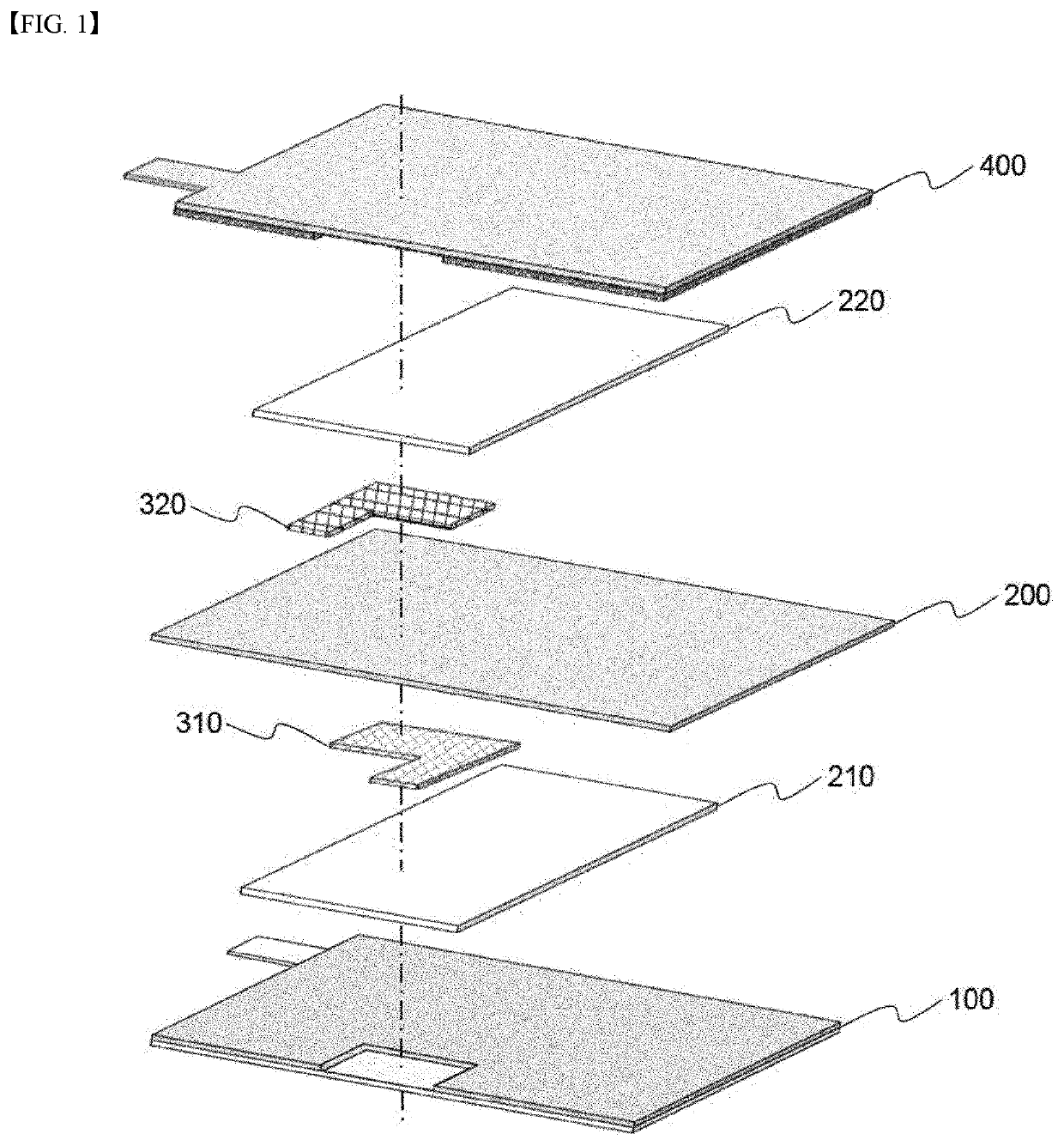
[0086]FIG. 1 is an exploded perspective view of a battery cell for evaluating an internal short circuit according to an embodiment of the present invention. Referring to FIG. 1, the battery cell has a structure in which a first electrode 100, a first sub-separator 210, a first short circuit electrode 310, a main separator 200, a second short circuit electrode 320, a second sub-separator 220, and a second electrode 400 are sequentially stacked. The first electrode 100 has a structure in which a non-coated part is formed on a part of the surface of the first electrode. The first sub-separator 210 has a structure which covers the non-coated part formed in the first electrode 100 and is extended in a right direction. The first short circuit electrode 310 is located on the first sub-separator 210. The first short circuit electrode 310 is formed of a porous metal foil, has a size corresponding to the non-coated part of the first electrode 100, and has a tab protruding in the left side of ...

second embodiment

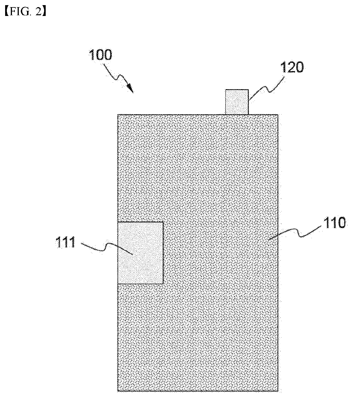
[0088]FIGS. 2 to 9 are diagrams illustrating assembling procedures of a battery cell for evaluating an internal short circuit according to one embodiment of the invention. Referring to FIG. 2, the first electrode 100 is formed of an aluminum foil and has a first electrode tab 120 protruding in the right upper direction, and the portion other than the first electrode tab 120 is the first electrode coated part 110 on which the electrode mixture layer is applied. The first electrode non-coated part, to which the electrode mixture layer has not been applied, is formed in the left center portion of the first electrode coated part 110. The area where the first electrode non-coated part 111 is formed corresponds to about 8% of the area of the first electrode coated part 110.

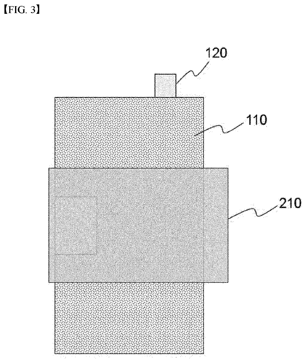
[0089]Referring to FIG. 3, the first sub-separator 210 is stacked on the first electrode 100 of FIG. 2. The first sub-separator 210 has a structure which covers the first electrode non-coated part 111 and is extended in...


PUM


Abstract

The present invention relates to a battery cell for evaluating an internal short circuit, and a method for evaluating using the battery cell, wherein an internal short circuit state of a battery cell can be easily induced and, at the same time, an effective internal short circuit evaluation is possible, and the battery cell comprising: first and second electrodes which comprise a coated region on which an electrode mixture layer is coated on a metal current collector and a non-coated region on which an electrode mixture layer is not coated, and which comprise first and second electrode tabs which protrude in one direction from the coated region and do not have an electrode mixture layer coated thereon.

Description

TECHNICAL FIELD[0001]The present invention relates to a battery cell for evaluating an internal short circuit and a method for evaluating an internal short circuit of a battery cell using the same.[0002]This application claims the benefit of priority based on Korean Patent Application No. 10-2019-0169230, filed on Dec. 17, 2019, and the entire contents of the Korean patent application are incorporated herein by reference.BACKGROUND ART[0003]In recent years, as the price of energy sources increases due to the depletion of fossil fuels and the interest of environmental pollution is amplified, the demand for environmentally friendly alternative energy sources has become an indispensable factor for future life. In particular, as technology development and demand for mobile devices increase, the demand for secondary batteries as energy sources is rapidly increasing.[0004]In general, a secondary battery assembles an electrode assembly by using a positive electrode, a negative electrode, a...

Claims


Application Information

Patent Timeline
IPC IPC(8): H01M50/574H01M10/0585H01M10/052H01M50/105H01M4/66H01M50/528H01M50/414H01M10/42H01M50/457H01M50/431H01M50/443H01M10/44H01M50/454
CPCH01M50/574H01M10/0585H01M10/052H01M50/105H01M4/661H01M50/528H01M50/414H01M10/4235H01M50/457H01M50/431H01M50/443H01M10/44H01M50/454H01M2200/00H01M10/058H01M10/4285H01M10/0525H01M50/409H01M50/449H01M10/42H01M50/572H01M4/13H01M10/48H01M50/44H01M50/451H01M50/569Y02E60/10G01R31/52H01M50/586H01M50/491H01M50/463H01M50/533H01M4/66H01M10/425H01M50/46H01M10/4214H01M50/59
Inventor LEE, SOL NIPYANG, JEONG MIN
Owner LG ENERGY SOLUTION LTD
Why Eureka
Try Eureka