Automated longitudinal position translator for ultrasonic imaging probes, and methods of using same

Inactive Publication Date: 2000-01-11
BOSTON SCI SCIMED INC
View PDF24 Cites 37 Cited by
  • Summary
  • Abstract
  • Description
  • Claims
  • Application Information

AI Technical Summary

Problems solved by technology

In practice, it is quite difficult for conventional ultrasonic imaging probes to obtain sufficiently closely spaced data samples of a section of a patient's vascular system under investigation since the reconstruction algorithms currently available depend upon the software's ability to process precisely longitudinally separated data samples.
Even with the most skilled physician, it is practically impossible manually to exercise constant rate longitudinal translation of the ultrasound imaging

Method used


Image

  • Automated longitudinal position translator for ultrasonic imaging probes, and methods of using same
  • Automated longitudinal position translator for ultrasonic imaging probes, and methods of using same
  • Automated longitudinal position translator for ultrasonic imaging probes, and methods of using same

Examples


Embodiment Construction

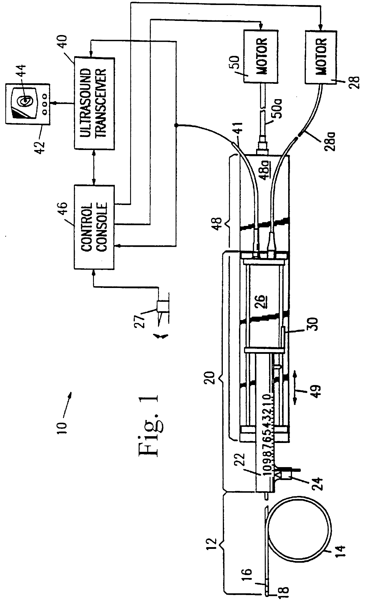
A schematic diagram of an exemplary ultrasound imaging system is shown in accompanying FIG. 1. System 10 generally includes an ultrasound imaging probe assembly 12 having a guide sheath 14 and a distally located ultrasound imaging probe element 16 inserted into the lumen of guide sheath 14, the probe element 16 being depicted in FIG. 1 as being visible through the, guide sheath's transparent wall. The ultrasonic imaging probe assembly 12 preferably embodies those features more fully described in the above-identified U.S. Pat. No. 5,115,814.

The overall length of the imaging probe assembly 12 is suitable for the desired diagnostic and / or therapeutic intravascular procedure. For example, the overall length of the probe assembly 12 may be shorter for direct (e.g., arteriotomy) insertions as compared to the length of the probe assembly 12 needed for percutaneous distal insertions (e.g., via the femoral artery). A representative length of the imaging probe assembly 12 is therefore shown i...


PUM


Abstract

A longitudinal position translator includes a probe drive module and a linear translation module. The probe drive module is coupled operatively to an ultrasonic imaging probe assembly having a distally located ultrasound transducer subassembly in such a manner that longitudinal shifting of the transducer subassembly may be effected. The probe drive module is preferably mounted to the linear translation unit so as to be moveable between a condition whereby longitudinal shifting of the transducer subassembly can be conducted either manually or automatically. When in the automatically-operable condition, the probe drive module will be engaged with a motor-driven screw associated with the linear translation module so as to cause the probe drive module to be longitudinally displaced at a constant motor-driven rate. In this manner, the distally located ultrasound transducer is longitudinally shifted during an ultrasound scan of surrounding intravascular (or other) tissue to thereby allow axially-spaced 360 DEG data sample "slices" of the surrounding tissue to be obtained. The data samples may then be reconstructed into a three-dimensional or other two-dimensional representations of the scanned vessel to assist in diagnosis.

Description

The present invention generally relates to elongate probe assemblies of sufficiently miniaturized dimensions so as to be capable of navigating tortuous paths within a patient's organs and / or vessels. In preferred forms, the present invention is embodied in automated units which are connectable to a probe assembly having a distally located ultrasound transducer subassembly which enables the transducer subassembly to be positioned accurately by an attending physician and then translated longitudinally (relative to the axis of the elongate probe assembly) within the patient under automated control.I. Introductory Background InformationProbe assemblies having therapeutic and / or diagnostic capabilities are being increasingly utilized by the medical community as an aid to treatment and / or diagnosis of intravascular and other organ ailments. In this regard, U.S. Pat. No. 5,115,814 discloses an intravascular probe assembly with a distally located ultrasonic imaging probe element which is po...

Claims


Application Information

Patent Timeline
IPC IPC(8): A61B8/12G01S15/89G01S15/00G01S7/521
CPCA61B8/12A61B8/4209A61B8/4461G01S7/52079G01S15/8936Y10S128/916
Inventor WEBLER, WILLIAM E.BUHR, MARK S.
Owner BOSTON SCI SCIMED INC
Why Eureka
Try Eureka