Method for printing label of optical disc using rainbow graphic cutting system

Inactive Publication Date: 2000-02-01
LG ELECTRONICS INC
View PDF6 Cites 71 Cited by
  • Summary
  • Abstract
  • Description
  • Claims
  • Application Information

AI Technical Summary

Problems solved by technology

In this case, if any title or any drawing must be label-printed on the surface of such a CD, there might arise distortion in the disc because of irregular spread or irregular pressure of printing ink thereon.
However, there are some problems in the method according to the prior art.
A first problem is that the drawing or the letter, which is intended to be printed on the optical disc, cannot be outputted to a monitor of the computer, since a printing location of the label is determined and stored in the text mode of the computer during editing.
Th

Method used


Image

  • Method for printing label of optical disc using rainbow graphic cutting system
  • Method for printing label of optical disc using rainbow graphic cutting system
  • Method for printing label of optical disc using rainbow graphic cutting system

Examples


Embodiment Construction

Reference will now be made in detail to the preferred embodiments of the present invention, examples of which are illustrated in the accompanying drawings.

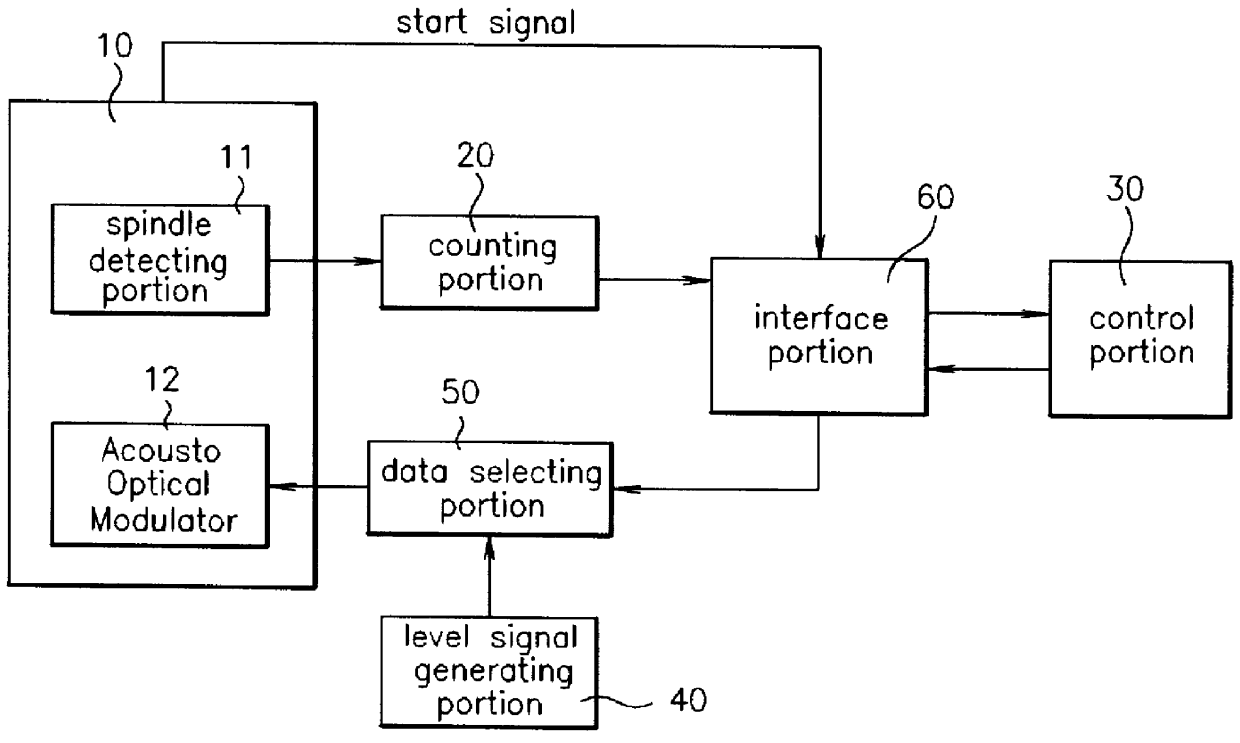
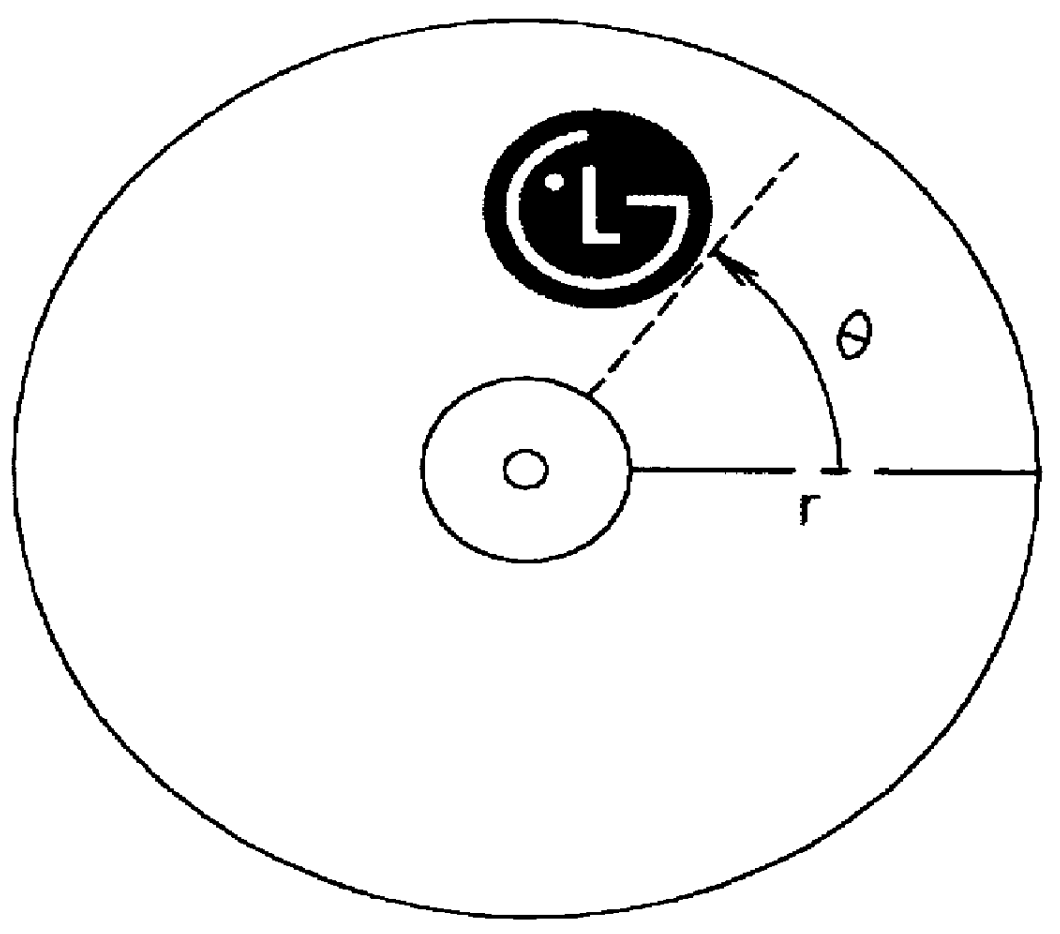
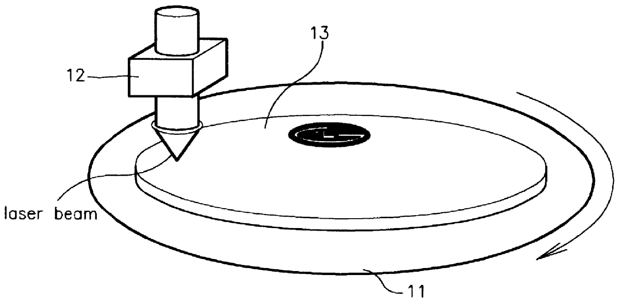
FIG. 1 is a diagram illustrating a file conversion principle of a label to be printed on the surface of an optical disc according to the present invention. FIG. 2 is a block diagram illustrating a label printing apparatus of the optical disc using of a rainbow graphic cutting system according to the present invention. And, FIG. 3 is a diagram illustrating a main part of a laser beam recorder.

Referring to FIGS. 2 and 3, there are provided in the label printing apparatus of the present invention, a spindle detecting portion 11, a laser beam recorder 10 LBR consisting of an acousto optical modulator 12 AOM, a counting portion 20, a control portion 30, a level signal generating portion 40, a data selecting portion 50, and an interface portion 60. The spindle detecting portion 11 generates a pulse signal which is used for detecting the...


PUM


Abstract

A method for printing a label on an optical disc using a rainbow graphic cutting system includes storing in a memory a location signal and color information data of the label to be printed on the surface of the optical disc. Corresponding location and data signals from among the location signals and the color information data are selectively output to a laser beam recorder LBR. A label corresponding to the signals output to the LBR is then printed on a surface of the optical disc.

Description

1. Field of the InventionThe present invention relates to an optical disc, and more particularly to a method for printing a label on the optical disc using a rainbow graphic cutting system (hereinafter, referred to as RGCS), which is used for printing a drawing or a letter on the surface of the optical disc by radiating laser light on the surface thereof.2. Discussion of Related ArtIn general, an optical disc can be called a compact disc (hereinafter, referred to as CD) whose diameter is 12 cm and whose memory capacity is 700MByte, thus being used as record media. In the manufacture process of the CD, a predetermined data is recorded on a glass substrate by radiating a laser beam thereon, the glass substrate being spread with photoresist. The surface of the glass substrate is developed and nickel is evaporated thereon. Thereafter, if the nickel is separated from the glass substrate, there is made a stamper which is the same as a record of the data. Finally, after resin is added to t...

Claims


Application Information

Patent Timeline
IPC IPC(8): B41J2/435G11B23/38G11B23/40G11B7/007
CPCB41J2/435G11B23/40B41J2/442G11B7/007
Inventor KIM, SEON-GYOUNG
Owner LG ELECTRONICS INC
Why Eureka
Try Eureka