Scribing tool

a technology of scriber and scriber, which is applied in the direction of writing aids, manufacturing tools, shaping tools, etc., can solve the problems of limited longevity of the prior art stylus assembly and a much longer useful li

Inactive Publication Date: 2000-02-08
MURRAY III WILLIAM W
View PDF9 Cites 22 Cited by
  • Summary
  • Abstract
  • Description
  • Claims
  • Application Information

AI Technical Summary

Problems solved by technology

The prior art stylus assembly is of very limited longevity.
Therefore, there exists a definite need to replace the prior art stylus and accompanying bushing with designs having much longer useful lives.

Method used


Image

  • Scribing tool
  • Scribing tool
  • Scribing tool

Examples


Embodiment Construction

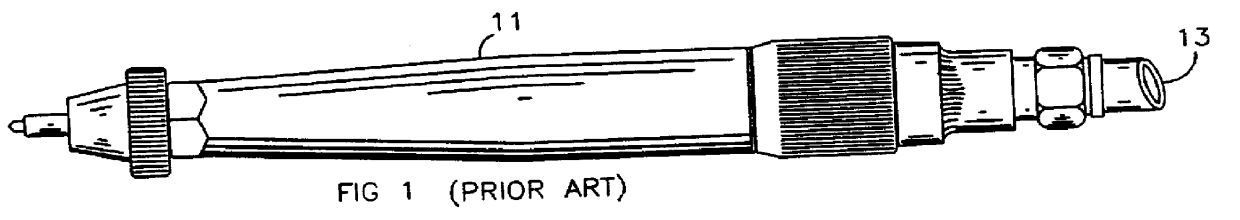
The inventive stylus-bushing assembly 10 is shown in FIGS. 8 and 8a installed within the open end of the handle portion 21 of housing 11 of a prior art pneumatic scribing tool. Outside diameter 29d of stylus bushing 20 of stylus assembly 10 is sized for press fitting within inside diameter 30d of handle portion 21 of outer shell housing 11. (FIGS. 8a and 9)

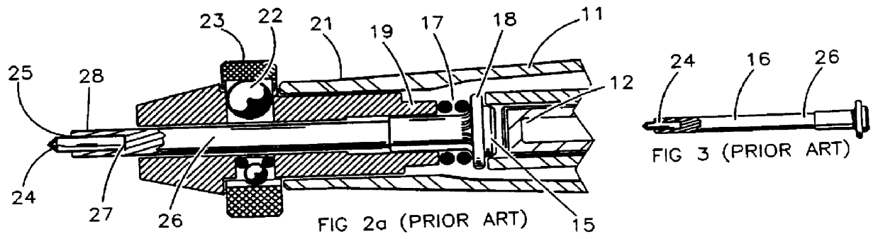
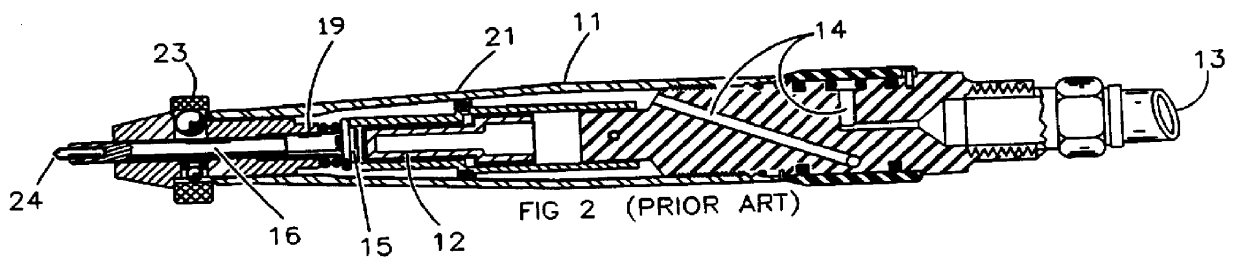
A reciprocating piston 12 is impelled first in one direction and then in the other within housing 11 by pressurized air provided through hose 13. The propelling air is directed through passages 14. Air passages in piston 12, not shown, alternately direct the air to impel the piston 12 to strike and withdraw from anvil end 15 of stylus assembly 16.

The stylus assembly 16 of the inventive stylus-bushing assembly 10 comprises an elongate, constant diameter stem portion 31 monolithic with a tapered scriber tip portion 28 made from a single piece of standard high impact grade solid tungsten carbide.

An open-ended steel sleeve 33 with an ...


PUM

PropertyMeasurementUnit
lengthaaaaaaaaaa
sizeaaaaaaaaaa
lengthaaaaaaaaaa

Abstract

An improved stylus assembly for replacing state of the art compressed air powered scribing tools, said stylus stem and point being monolithic and capable of operation indefinitely without failure of the stem, requiring only infrequent sharpening of the scribing tip.

Description

1. FieldThe field of the invention is stylus designs for handheld pneumatic scribers.2. Prior ArtThe prior art of hand-held pneumatic scribing devices is exemplified by the air scribe of FIGS. 1-7. (Prior art), having an outer shell housing 11, also serving as a handle, and a reciprocating piston 12 operated by compressed air provided from a flexible hose 13. The sliding piston is propelled into reciprocating motion by air from hose 13 provided through passages 14. The piston has passages therein, not shown, which are opened or closed according to the piston position to cause the piston to rapidly reciprocate, striking anvil end 15 of stylus assembly 16 repeatedly.O-rings 17 are utilized between flange 18 of stylus assembly 16 and a shoulder 19 of a stylus holding bushing 20 pressed into the open end of the handle portion of outer housing 11. The O-rings 17, compressed when the stylus assembly 16 is struck by the piston 12, act as a spring to return the stylus assembly toward the wi...

Claims


Application Information

Patent Timeline
Patent Type & Authority Patents(United States)
IPC IPC(8): B41C1/02
CPCB41C1/02Y10T83/9473
Inventor MURRAY, III, WILLIAM W.
Owner MURRAY III WILLIAM W
Why Eureka
Try Eureka