Flat knitting machine having a yarn feeding system

a knitting machine and yarn feeding technology, applied in knitting, weft knitting, textiles and papermaking, etc., can solve the problems of inevitably larger yarn feeding system, heavier weight, and complex mechanism

Inactive Publication Date: 2000-02-08
SHIMA SEIKI MFG LTD
View PDF8 Cites 48 Cited by
  • Summary
  • Abstract
  • Description
  • Claims
  • Application Information

AI Technical Summary

Problems solved by technology

However, if yarn feeders of all of multiple yarn carriers arranged on a carrier rail are positioned close to the top end of a needle, when a yarn carrier that is moving crosses a yarn carrier that is standing, their yarn feeders will collide with each other or their yarn feeders will collide with a needle or a sinker.
The resulting yarn feeding system is inevitably larger in size, more complex in mechanism and heavier in weight.

Method used


Image

  • Flat knitting machine having a yarn feeding system
  • Flat knitting machine having a yarn feeding system
  • Flat knitting machine having a yarn feeding system

Examples


Embodiment Construction

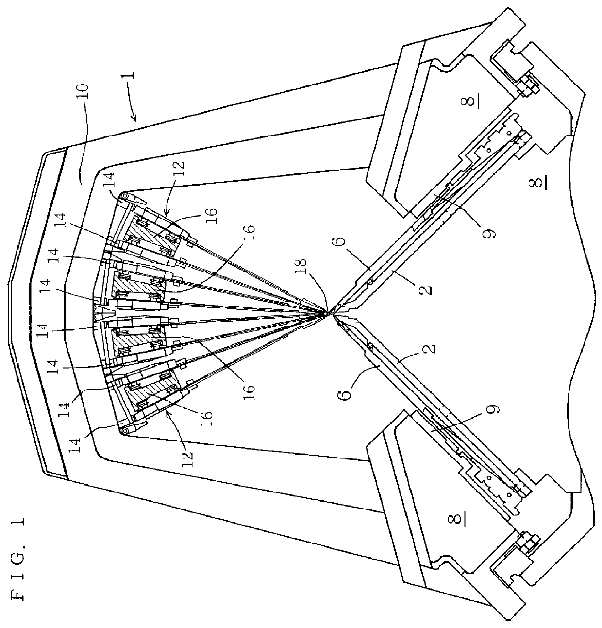
Some embodiments will be described with reference to the attached drawings. FIG. 1 is a side view of a flat knitting machine having a yarn feeding system according to the present invention, and 1 denotes the flat knitting machine generally.

In this flat knitting machine 1, top ends of a pair of needle beds 2, one in the front and one in the rear, are opposed to each other on a frame 4, with the needle beds 2 forming an inverted V when seen from the side. Plural needles 6 are mounted on each needle bed 2 so that these needles 6 can be moved forward and backward. Carriages 8 are driven, by a belt driving means not illustrated, over the tops of the needle beds 2 to reciprocate and move needles 6 forward or backward through knitting cams 9 mounted on the carriages 8. The carriages 8 are integrally provided with a gate arm 10 that strides over the front and back needle beds 2. A catching member 14 for catching a yarn carrier 12 is mounted on the gate arm 10.

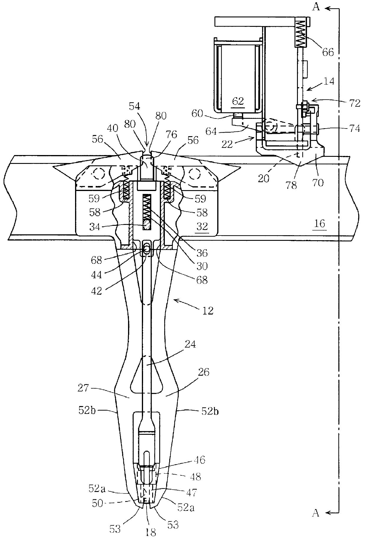
Four carrier rails 16 are suppo...


PUM


Abstract

Plural carrier rails are arranged radially relative to a trick gap, and yarn carriers are made to run on the rails. In the yarn carrier, a feeder rod is mounted on a yarn rod guide so that the the rod can slide up and down. The feeder rod is pushed up by a spring coil, and the feeder rod is pushed down by a catching member toward the trick gap.

Description

The present invention relates to a yarn feeding system for a flat knitting machine that feeds yarn to needles provided on needle beds.PRIOR ARTWhen multiple color yarns or yarns of various kinds are used in knitting, a carrier rail is provided above needle beds along the longitudinal direction thereof, and multiple yarn carriers are supported on this rail. And a carriage is made to reciprocate over the needle beds to actuate needles.At the time of knitting, when a needle arranged on a needle bed is made to protrude into a yarn feeding position, a yarn feeder having a yarn feeding eyelet provided at the lower end of a yarn carrier must feed yarn at a point close to the top end of the needle. However, if yarn feeders of all of multiple yarn carriers arranged on a carrier rail are positioned close to the top end of a needle, when a yarn carrier that is moving crosses a yarn carrier that is standing, their yarn feeders will collide with each other or their yarn feeders will collide with...

Claims


Application Information

Patent Timeline
Patent Type & Authority Patents(United States)
IPC IPC(8): D04B15/38D04B15/56D04B15/48
CPCD04B15/56D04B7/26D04B15/80
Inventor SHIMA, MASAHIRO
Owner SHIMA SEIKI MFG LTD
Why Eureka
Try Eureka