Laser range finder with target quality display and scan mode

a laser range finder and target quality technology, applied in the field of handheld laser range finders, can solve the problems of high cost of processors capable of operating at this clock speed, short time period, and high cost of accurate distance ranging. achieve the effect of accurate aiming, high-quality target range and economical cos

Inactive Publication Date: 2000-02-08
BUSHNELL CORPORATION
View PDF27 Cites 89 Cited by
  • Summary
  • Abstract
  • Description
  • Claims
  • Application Information

AI Technical Summary

Benefits of technology

The principle objects and advantages of the present invention include: to provide an improved laser range finder; to provide such a laser range finder which emits a series of laser pulses toward a target with each engagement of a fire switch; to provide such a laser range finder which detects each identifiable reflected return pulse from said series; to provide such a laser range finder with a target quality indicator indicating the number of returned pulses or the ratio of the number of returned pulses vs. the number of emitted pulses; to provide such a laser range finder with a reticle which approximates the footprint of the emitted laser pulses for accurately aiming the range finder; to provide such a laser range finder which is capable of using a relatively slow sampling clock to determine highly accurate target ranges; to provide such a laser range finder with a circular field of view; to provide such a range finder with a magnified "TV view" of the target area which forms a portion of the circular field of view; to provide such a laser range finder which can be produced at an economical cost, enabling sales to a mass consumer market; to provide such a range finder which includes a mode selector switch; to provide such a range finder in which one of the modes selectable by the mode selector switch is a Scan mode; and to provide such a laser range finder which is attractive, rugged, reliable and which is particularly well suited for its intended purpose.

Problems solved by technology

One problem with prior art range finders is that the measured time periods are so short that extremely fast clocks and very sophisticated circuitry are required for accurate distance ranging.
Processors capable of operating at this clock speed are expensive, which effectively prices typical prior art range finders well beyond the mass consumer market.
However, without information relating to target quality, a user of such a range finder would not be able to isolate the reason for a lack of a distance reading, i.e. low battery, equipment malfunction, target quality, etc.
This does not allow a user to scan an area to rapidly, sequentially determine the distance to a variety of targets.

Method used


Image

  • Laser range finder with target quality display and scan mode
  • Laser range finder with target quality display and scan mode
  • Laser range finder with target quality display and scan mode

Examples


Embodiment Construction

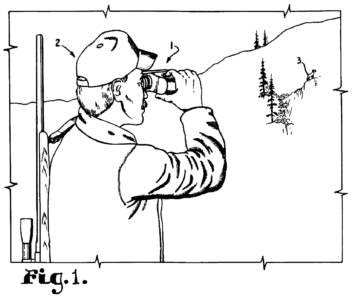
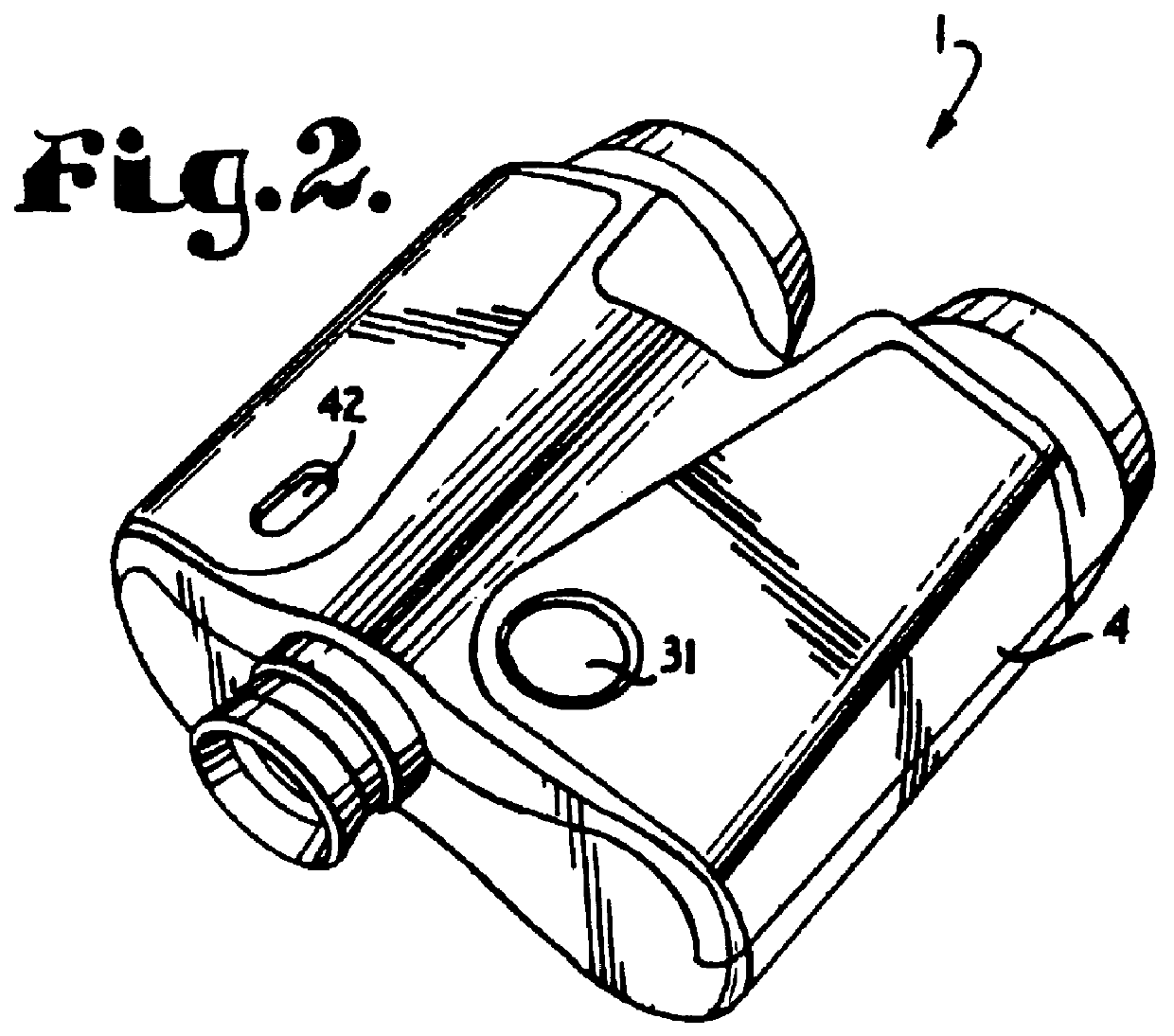
I. Introduction and Environment

As required, detailed embodiments of the present invention are disclosed herein; however, it is to be understood that the disclosed embodiments are merely exemplary of the invention, which may be embodied in various forms. Therefore, specific structural and functional details disclosed herein are not to be interpreted as limiting, but merely as a basis for the claims and as a representative basis for teaching one skilled in the art to variously employ the present invention in virtually any appropriately detailed structure.

Certain terminology will be used in the following description for convenience in reference only and will not be limiting. For example, the words "up", "down", "right" and "left" will refer to directions in the drawings to which reference is made. The words "inward" and "outward" will refer to directions toward and away from, respectively, the geometric center of the embodiment being described and designated parts thereof. Said termino...


PUM


Abstract

A laser range finder includes a circular in-sight field of view which incorporates within it a magnified "TV view" of the target area with the TV view roughly approximating the rectangular shape of a standard television picture. Also within the circular field, over and under the TV view, are a target quality indicator, a range distance display, and other indicators. Within the TV view is a targeting reticle which indicates roughly the footprint of ranging laser pulses such that a target can be selected. The target quality indicator is a bar graph which displays the number of identifiable received reflected laser pulses from a series of such pulses emitted by the range finder. By aiming the range finder at various targets via the footprint reticle, repeatedly firing the range finder and monitoring the target quality graph for each firing, a user can move the range finder to find a surface proximate the target with a reflective quality sufficient to yield an accurate target range reading. Alternatively, with a range finder equipped with Scan mode capability, the range finder can be slowly panned across multiple targets with the range to each target being displayed, in sequence, on the range display.

Description

1. Field of the InventionThis invention is directed to a hand-held laser range finder, and, more particularly, to such a range finder with a TV-type viewing field and a reticle representing the laser footprint and with a target quality bar graph display. The range finder has a mode setting switch which selects one of a plurality of modes, including a scan mode.2. Description of the Related ArtLaser range finders have been manufactured for a number of years. Typically such range finders send a laser pulse and receive the pulse as reflected from a target. An internal clock monitors the time difference between the transmitted and received pulses, halves the time difference and multiplies it by the speed of light to thereby derive a distance from the range finder to the target.One problem with prior art range finders is that the measured time periods are so short that extremely fast clocks and very sophisticated circuitry are required for accurate distance ranging. Ideally a range finde...

Claims


Application Information

Patent Timeline
Patent Type & Authority Patents(United States)
IPC IPC(8): G01C3/08G01S17/10G01S17/00G01S7/51G01S7/48G01S7/481G01S7/497G01S17/14
CPCG01C3/08G01S7/4811G01S7/51G01S17/105G01S7/4873G01S7/497G01S17/14
Inventor BAMBERGER, STEPHEN J.
Owner BUSHNELL CORPORATION
Why Eureka
Try Eureka