

Synchronous motor with movable part having permanent magnets
a technology of synchronous motors and permanent magnets, which is applied in the direction of dynamo-electric machines, electrical apparatus, magnetic circuit shapes/forms/construction, etc., can solve the problems of insufficient effective use, difficult high-speed drive of linear motors, and insufficient effective magnetic flux
- Summary
- Abstract
- Description
- Claims
- Application Information
AI Technical Summary
Problems solved by technology
Method used
Image

Examples
first embodiment
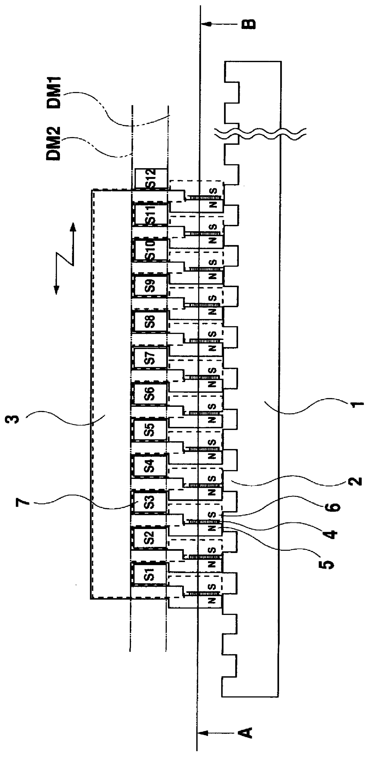
A cross-sectional view of a linear motor in accordance with this invention is shown in FIG. 1.
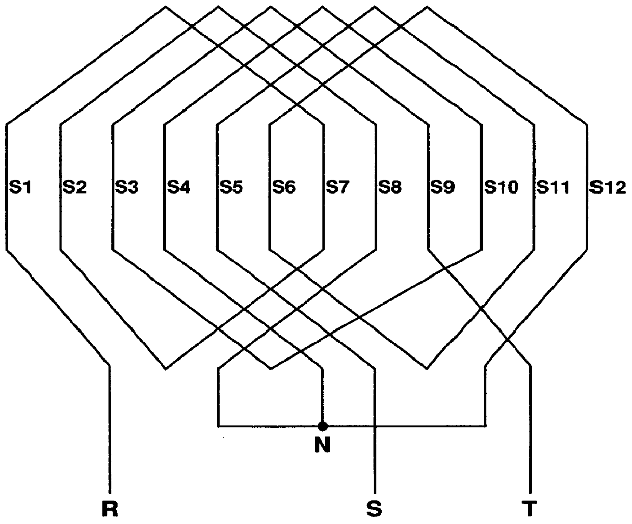
3 is a slider which forms a movable part and 7 is one of the slots on the slider 3 indicated by S1 to S12. A bipolar three-phase alternating current winding, commonly used for such a rotation-type induction motor, is wound to be aligned in a line in each slot. FIG. 3 illustrates a concrete example of their wire-wound diagram. R, S, and T are terminals of three-phase alternating current windings, and N is a neutral point just as in the case with the linear motor illustrated in FIG. 11 of a prior art.
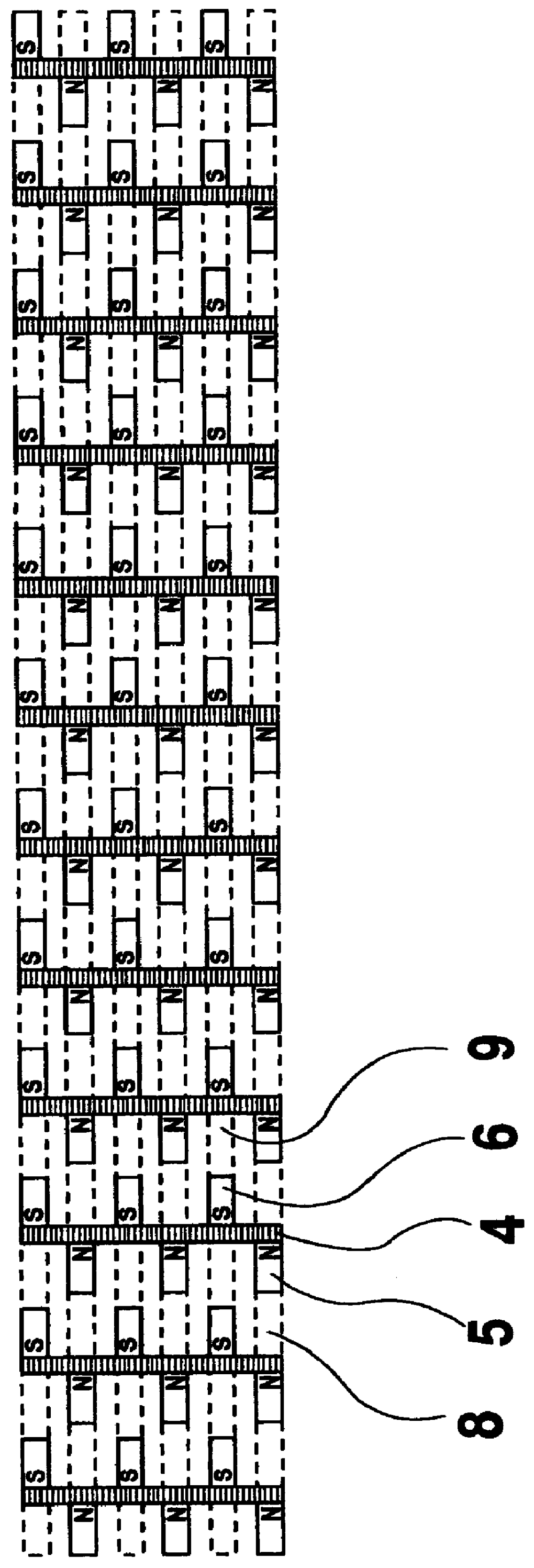
The slider 3 is shaped rather complicated and has 12 sets of the magnetic pole N and the magnetic pole S placed side by side in the traverse direction of the slider shown by the arrow, in other words the side-to-side direction on the paper. 4 is a permanent magnet whose magnetism direction points the direction of hatched line and whose magnetic polarity is indicated in the figure as N and S. The ...
third embodiment
The sectional view of the linear motor that is this invention is depicted in FIG. 7. A cross-sectional view of section I-J is illustrated in FIG. 8 and that of section K-L is in FIG. 9. Basic concept of this embodiment is identical with the linear motor shown in FIG. 4 but individual permanent magnets 4 are not attached in the place close to a slider surface and a common permanent magnet 13 indicated in FIG. 9 is attached, as a substitute for those, between a magnetic yoke for the north pole 8 and a magnetic yoke for the south pole 9 within a slider.
The operation of the motor of the third embodiment is similar to the linear motor shown in FIG. 1 and FIG. 4 and, as stated above, a common permanent magnet 13 attached within a slider supplies magnetic flux to each magnetic north pole 5, auxiliary magnetic north pole 12, each magnetic south pole 6, and auxiliary magnetic south pole 10. In comparison to the linear motor shown in FIG. 1 or FIG. 4, the linear motor in the third embodiment ...
PUM
 Abstract
Description
Claims
Application Information