Memory device having a pipe counter

Inactive Publication Date: 2000-02-15
HYUNDAI ELECTRONICS IND CO LTD
View PDF1 Cites 3 Cited by
  • Summary
  • Abstract
  • Description
  • Claims
  • Application Information

AI Technical Summary

Problems solved by technology

However, the pipe counter operating as above involves some problems in constructing the circuit so as to operate only in read mode.
In other words, the problem is that the circuit as constructed is automatically operated when the power is turned on and the LRAS signal is at a high level.
Therefore, there is the problem that the driving current of the transistors is increased and a large layout is necessary for the large transistors.

Method used


Image

  • Memory device having a pipe counter
  • Memory device having a pipe counter
  • Memory device having a pipe counter

Examples


Embodiment Construction

A preferred embodiment of the present invention will be explained in detail by reference to the accompanying drawings.

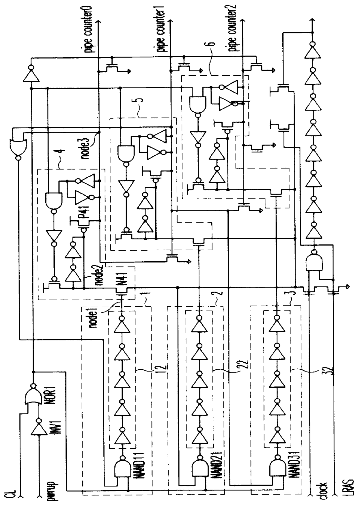
FIG. 3 shows a pipe counter circuit incorporated into a memory device of the present invention.

As shown in the drawing, the pipe counter includes a NAND-gate NAND1 for NANDing a clock signal CLK and a LRAS signal which are applied externally; a NOR-gate NOR1 for NORing a column latency signal CL and a power signal PWRUP passed through an inverter INV1; a plurality of flip-flops 10, 20 and 30, each of the clock terminals / C, C of which receives the signal outputted from the NAND-gate NAND1 and the signal outputted from the inverter INV3, respectively, and each of the reset terminals of which receives the signal passed through an inverter INV2 which inverts the signal outputted from the NOR-gate NOR1; and an NOR-gate NOR2 for NORing the output Q of the first flip-flop 10 and the output Q of the second flip-flop 20.

Next, the input / output relationship of the first, secon...


PUM


Abstract

The present invention discloses a memory device having a pipe counter. It provides the advantages in that it can reduce by about 50% the number of transistors needed in constructing a pipe counter while performing the same functions as a conventional pipe counter, thereby reducing the circuit area and decreasing the driving current of the counter, by applying the concept of a ring counter to a pipe counter used in a data output terminal of DRAM.

Description

1. Field of the InventionThe present invention relates to a memory device having a pipe counter. In particular, the present invention relates to a memory device having a pipe counter which can perform the same functions as a conventional pipe counter while reducing the circuit area and decreasing the driving current of the counter, by applying the concept of a ring counter to a pipe counter used in a data output terminal of DRAM.2. Description of the Prior ArtTypically, counters used in the data output terminals of DRAM employ pipe counters.A schematic diagram of a conventional pipe counter circuit is shown in FIG. 1. As shown in FIG. 1, a conventional pipe counter includes a NOR-gate NOR1 for NORing a column latency CL signal and a power signal passed through an inverter INV1 so as to output the resulting signals to pipe counter input terminals 1, 2 and 3, respectively; pipe counter input terminals 1, 2 and 3 having NAND-gates 11, 21 and 31 for NANDing the signals output from the N...

Claims


Application Information

Patent Timeline
IPC IPC(8): G11C8/04
CPCG11C8/04G11C11/401
Inventor LEE, MYONG DON
Owner HYUNDAI ELECTRONICS IND CO LTD
Why Eureka
Try Eureka