Non-volatile latch circuit that has minimal control circuitry

Inactive Publication Date: 2003-10-28
FAIRCHILD SEMICON CORP
View PDF3 Cites 14 Cited by
  • Summary
  • Abstract
  • Description
  • Claims
  • Application Information

AI Technical Summary

Problems solved by technology

A drawback with this type of latch circuit is that the dedicated control circuitry is complex and cons

Method used


Image

  • Non-volatile latch circuit that has minimal control circuitry
  • Non-volatile latch circuit that has minimal control circuitry
  • Non-volatile latch circuit that has minimal control circuitry

Examples


Embodiment Construction

A. Structure of Non-volatile Latch Circuit

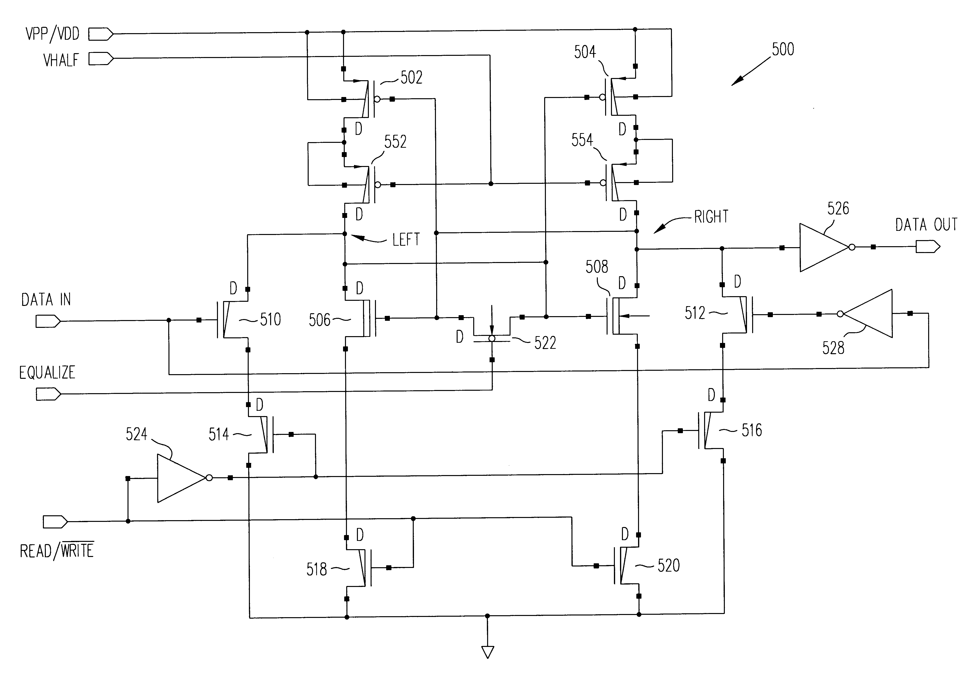
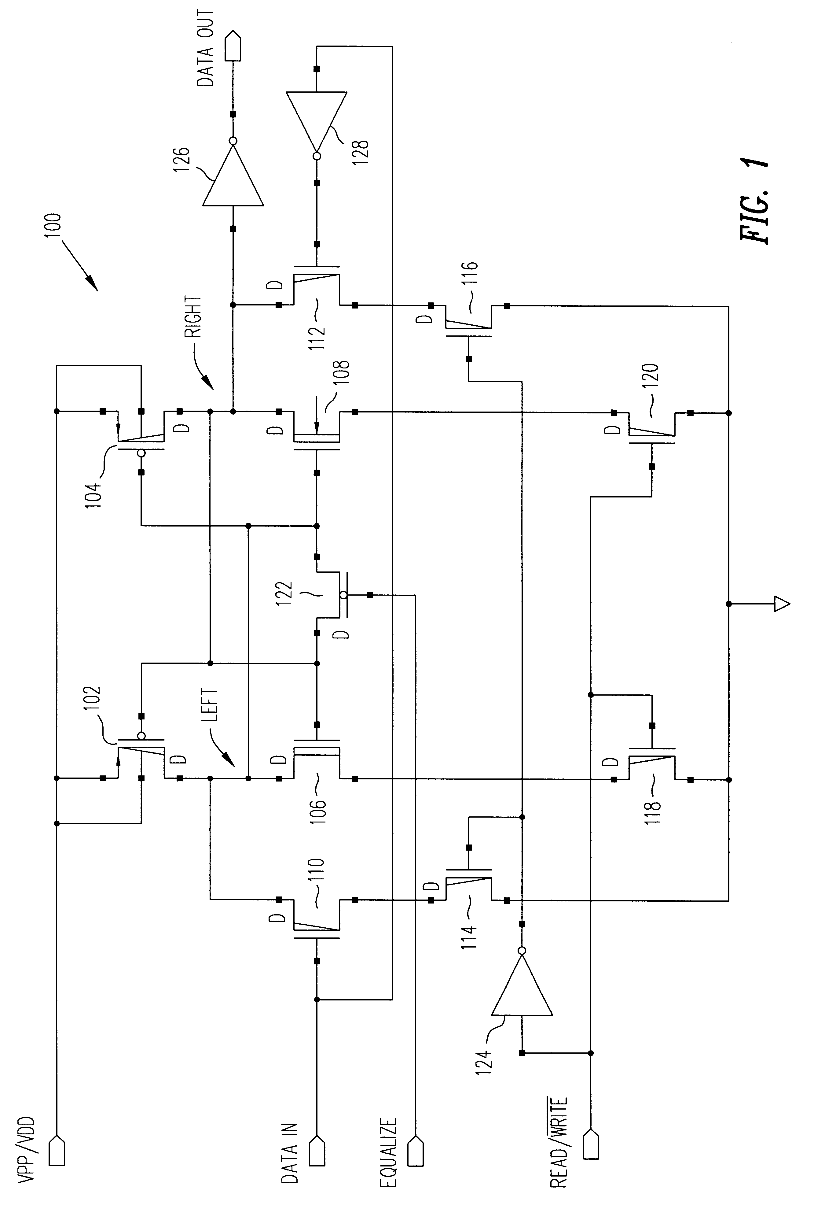
FIG. 1 is a schematic diagram of a non-volatile latch circuit 100 having minimal control circuitry, according to some embodiments of the present invention. Non-volatile latch circuit 100 is capable of storing a bit of data (i.e., a logic 1 or a logic 0). Typically, several non-volatile latch circuits 100 (e.g., less than 32) will be incorporated into an integrated circuit device to provide storage for relatively few bits of data. An advantage of non-volatile latch circuit 100 is that it occupies a relatively small amount of chip area / volume when compared to conventional non-volatile latch circuits. This is due to a reduction in the amount of control signals and control circuitry used to control non-volatile latch circuit 100. As mentioned above, some conventional non-volatile latch circuits (including their control circuitry) are implemented using 38 transistors, whereas non-volatile latch circuit 100 of the present invention (including its ...


PUM


Abstract

A non-volatile latch circuit that has minimal control circuitry is disclosed. The non-volatile latch circuit is typically used in applications where only several bits of data need to be stored in non-volatile memory. The non-volatile latch circuit can be programmed and read using three control signals: a programming voltage/supply voltage signal, a data in signal, and a read/{overscore (write signal. By using fewer control signals, the number of transistors used to implement the control circuitry within the non-volatile latch circuit is reduced and thus the non-volatile latch circuit consumes less chip area/volume on an integrated circuit device.

Description

1. Field of the InventionThe present invention relates to integrated circuit devices and, more particularly, to a non-volatile latch circuit that has minimal control circuitry.2. Related ArtSemiconductor memory can be classified as either volatile or non-volatile memory. Volatile memory loses its stored information when power is removed from the memory, whereas non-volatile memory retains its stored information when power is removed from the memory. One common type of non-volatile memory is known as a non-volatile latch circuit. A non-volatile latch circuit is capable of storing one bit of data (i.e., a logic 1 or a logic 0).Non-volatile latch circuits can be classified as non-dedicated control circuitry or dedicated control circuitry non-volatile latch circuits. Non-dedicated control circuitry non-volatile latch circuits are used in applications where many bytes of data (e.g., thousands of bytes) need to be stored. These non-volatile latch circuits are typically arranged in a two-d...

Claims


Application Information

Patent Timeline
IPC IPC(8): G11C16/06
CPCG11C16/10
Inventor RAPP, A. KARLHOU, HUNGYU H.
Owner FAIRCHILD SEMICON CORP
Why Eureka
Try Eureka