Intraocular lens and method for preventing secondary opacification

a technology of intraocular lens and secondary opacification, which is applied in the field of intraocular lens, can solve the problems of not having the property of preventing secondary opacification of the posterior capsule, increasing the complication rate after cataract surgery to the level, and not having the ability to prevent further cellular proliferation, etc., to achieve the effect of improving the stability of lens fixation, reducing weight, and increasing stability

Inactive Publication Date: 2000-02-22
TASSIGNON MARIE JOSE B R
View PDF12 Cites 185 Cited by
  • Summary
  • Abstract
  • Description
  • Claims
  • Application Information

AI Technical Summary

Benefits of technology

C. The calibration of the anterior and posterior capsular opening is important since the opening will have to be slightly smaller than the circumference of the inner diameter of the lens groove in order to stretch the capsular openings when inserting the lens. This stretching of the rims of the capsular openings will block the proliferation of the cells that will be captured in a closed space or environment, provided by the circular equatorial groove. We now know experimentally that cell proliferation is inhibited in a closed space. Additionally, this stretching will induce a further coalescence of anterior and posterior capsular layers and cause circular traction folds in which the proliferating cells are captured.
D. It is also known experimentally that a circular opening in the lens capsules will

Problems solved by technology

None of these lenses have the property of preventing the secondary opacification of the posterior capsule of the lens bag.
These secondary capsulotomies however increase the complication rate after cataract surgery to the level of the older, now mostly abandoned intracapsular technique of cataract extraction.
They are all placed

Method used


Image

  • Intraocular lens and method for preventing secondary opacification
  • Intraocular lens and method for preventing secondary opacification
  • Intraocular lens and method for preventing secondary opacification

Examples


Embodiment Construction

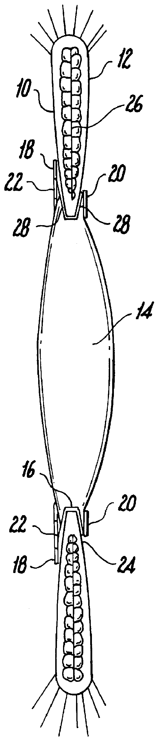
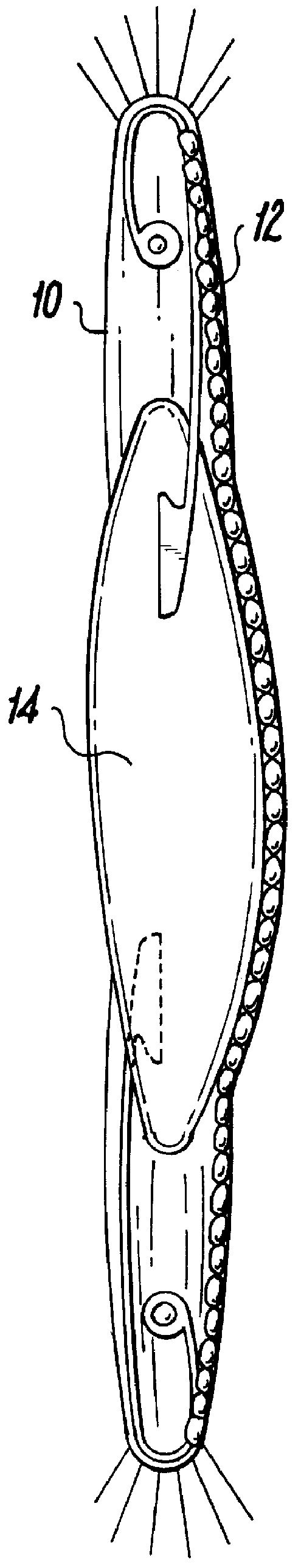
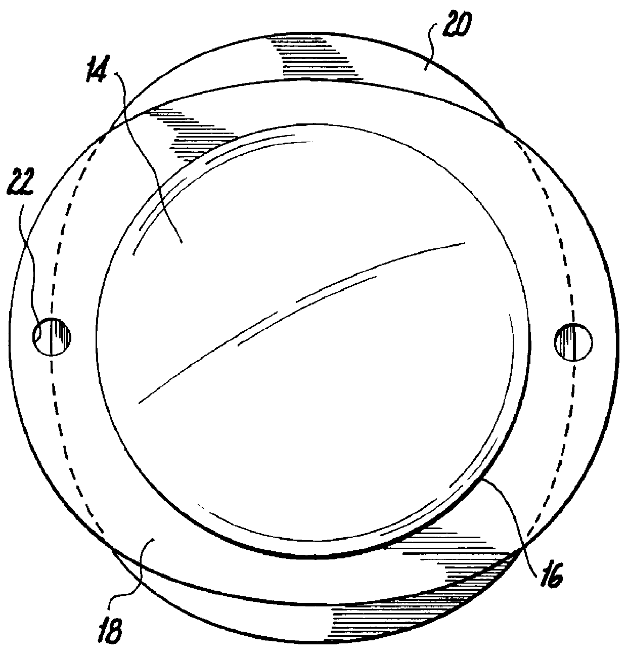
FIGS. 1A and 1B illustrate the difference in concept of the lens in-the-bag fixation technique, FIG. 1A, as currently used by ocular surgeons, and the novel bag-in-the-lens fixation technique, FIG. 1B. In order to realize this new principle of lens fixation, the lens design has been changed as shown in FIGS. 2A, 2B and 2C. The preferred embodiment of the optical pat 14 of the intraocular lens is circular and biconvex although other configurations and shapes may be employed. The optical part 14 of the intraocular lens may be constructed of any of the currently used materials for rigid optics such as polymethylmetacrylate (PMMA), or deformable optics such as silicone polymeric materials, acrylic polymeric materials, hydrogel forming polymeric materials and mixtures of these materials or the like. The lens materials used can be coated with chemicals for various purposes, as illustrated in the prior art. The diameter of the optical part 14 of the intraocular lens can be variable but sho...


PUM


Abstract

An intraocular lens for use in extracapsular cataract extraction has a haptic pat that surrounds the optical pat of the lens and further contains a groove of such shape to accommodate the anterior and posterior capsules of the lens bag after anterior capsulorhexis, extracapsular cataract extraction and posterior capsulorhexis. The lens is preferably inserted in a calibrated, circular and continuous combined anterior and posterior capsulorhexis, slightly smaller than the inner circumference of the groove as to induce a stretching of the rims of the capsular openings. This new approach is believed to prevent the appearance of secondary opacification of the capsules, allows a very stable fixation of the intraocular lens and ensures a tight separation between the anterior and posterior segment of the eye. This new principle of insertion is called the bag-in-the-lens technique, in contrast with the classical lens in-the-bag technique.

Description

1. Field of the InventionThis invention relates generally to the field of intraocular lenses after cataract extraction and in particular to intraocular lenses that reduce secondary opacification of the lens capsules.2. Description of Prior ArtThe insertion of an artificial intraocular lens in the human eye is a well-known surgical procedure to cure cataract, a common eye disorder in which the natural lens becomes gradually less transparent.Typically in such a procedure, the opaque lens material is removed from the lens bag, and is replaced by an artificial intraocular lens with the same optical properties. Several lens types have been designed since the original idea of Ridley in 1949. These types include e.g. anterior chamber angle supported lenses, iris supported lenses, posterior chamber sulcus fixated lenses, and in-the-bag lenses. None of these lenses have the property of preventing the secondary opacification of the posterior capsule of the lens bag. This secondary opacificati...

Claims


Application Information

Patent Timeline
IPC IPC(8): A61F2/16A61F2/00
CPCA61F2/1613A61F2002/009A61F2002/1681A61F2002/1697A61F2002/1699A61F2002/169A61F2/16
Inventor TASSIGNON, MARIE-JOSE B. R.
Owner TASSIGNON MARIE JOSE B R
Why Eureka
Try Eureka