

Three-phase permanent magnet cascade claw type stepping motor
a permanent magnet, claw-type technology, applied in the direction of dynamo-electric machines, magnetic circuit rotating parts, magnetic circuit shapes/forms/construction, etc., can solve the problems of large oscillation and noise of two-phase hybrid type stepping motors, high cost and complicated circuits, etc., and achieve small oscillation and noise.
- Summary
- Abstract
- Description
- Claims
- Application Information
AI Technical Summary
Benefits of technology
Problems solved by technology
Method used
Image

Examples
first embodiment
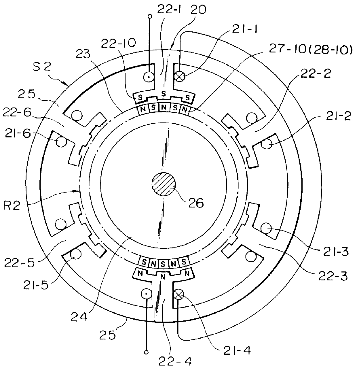
A three-phase six-pole permanent magnet type stepping motor 20 according to this invention will be explained with reference to FIG. 1.
The permanent magnet type stepping motor 20 shown in FIG. 1 has a stator S2 and a rotor R2. The stator S2 comprises an annular stator yoke 25 and 6 m pieces of stator main magnetic pole 22-1-22-6 equidistantly apart from one another and extending inwardly radially from the inner peripheral surface of the annular stator yoke 25, where m is an integer and .gtoreq.1. Three-phase stator windings 21-1-21-6 are wound around the stator main magnetic poles. On the outer peripheral surface of the rotor R2, twenty five N pole 27-10 and twenty five S poles 28-10 are magnetized alternately.
The inner peripheral surfaces of the stator main poles 22-1-22-6 are faced the outer peripheral surface of the rotor R2 with a small gap therebetween. Each stator main pole has three pole teeth 22-10 on the inner peripheral surface thereof.
In the present invention the number Z ...
second embodiment
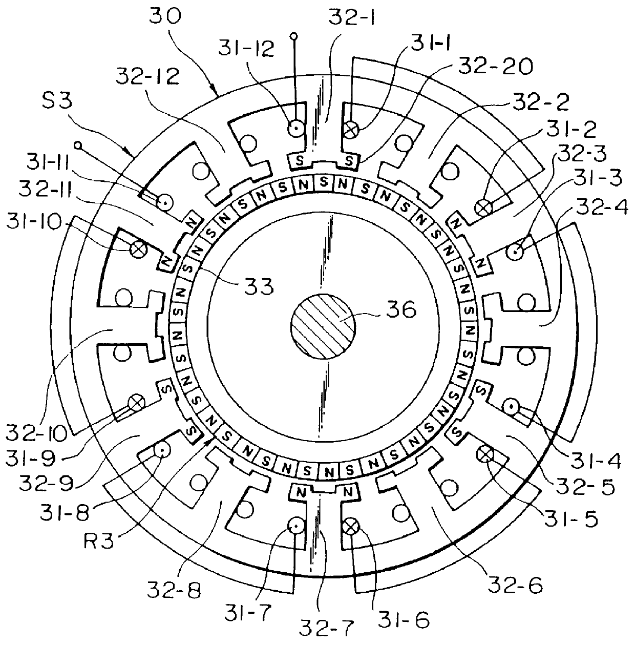
the twelve-pole two-phase permanent magnet type stepping motor 30 according to the present invention will be explained with reference to FIG. 2.
A rotor R3 is similar in construction to the rotor R2 shown in FIG. 1 and consisting of a cylindrical permanent magnet 33 having a plurality of N poles and S poles alternately on the outer periphery thereof.
A stator S3 has twelve main poles 32-1-32-12 arranged equidistantly apart from one another, and two-phase windings 31-1-31-12 are wound around the stator main poles. One-phase windings are wound around every one of the main poles among the twelve main poles 32-1-32-12, and three of N poles and three of S poles are formed alternately on the six main poles when the one-phase windings are excited with a direct current.
FIG. 2 shows polarities with respect to only one-phase windings. In the stepping motor shown in FIG. 2 forces acting on the rotor R3 in the radial direction are always cancelled with each other similar to that shown in FIG. 1.
E...
third embodiment
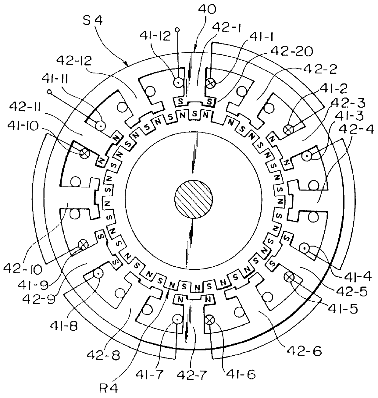
the twelve poles two-phase hybrid type stepping motor 40 according to the present invention will be explained with reference to FIG. 3.
A stator S4 is similar in construction to the stator S3 of the second embodiment of the present invention, but a rotor R4 is of hybrid type.
The oscillation and the noise of the hybrid type stepping motor become larger than that shown in FIG. 2.
However, the number of main poles of this embodiment according to the present invention becomes larger than that of the conventional stepping motor shown in FIG. 4 of which number of the main poles is eight, so that the electromagnetic forces acted on the rotor R4 are balanced.
Three stator main poles 42-1, 42-5 and 42-9 arranged with a pitch of 120.degree. are the same polarity and attract the rotor magnetic poles of opposite polarity, so that the total of vectors of the radial forces becomes zero and is expressed by
The merit of the hybrid type motor is to reduce the step angle .theta.s compared with that using...
PUM
 Abstract
Description
Claims
Application Information