
Amplifier circuit for AM broadcasting

an amplifier circuit and am-based technology, applied in the field of am-based amplifier circuits, can solve the problems of not being able to reduce the size of an entire circuit, not being able to integrate an rf amplifier with another rf circuit, and not being able to construct an rf amplifier with a cmos circuit, etc., to achieve the effect of suppressing flicker noise, small size and low noise of the entire circui

Inactive Publication Date: 2006-05-02
RICOH KK
View PDF15 Cites 2 Cited by
  • Summary
  • Abstract
  • Description
  • Claims
  • Application Information

AI Technical Summary

Benefits of technology

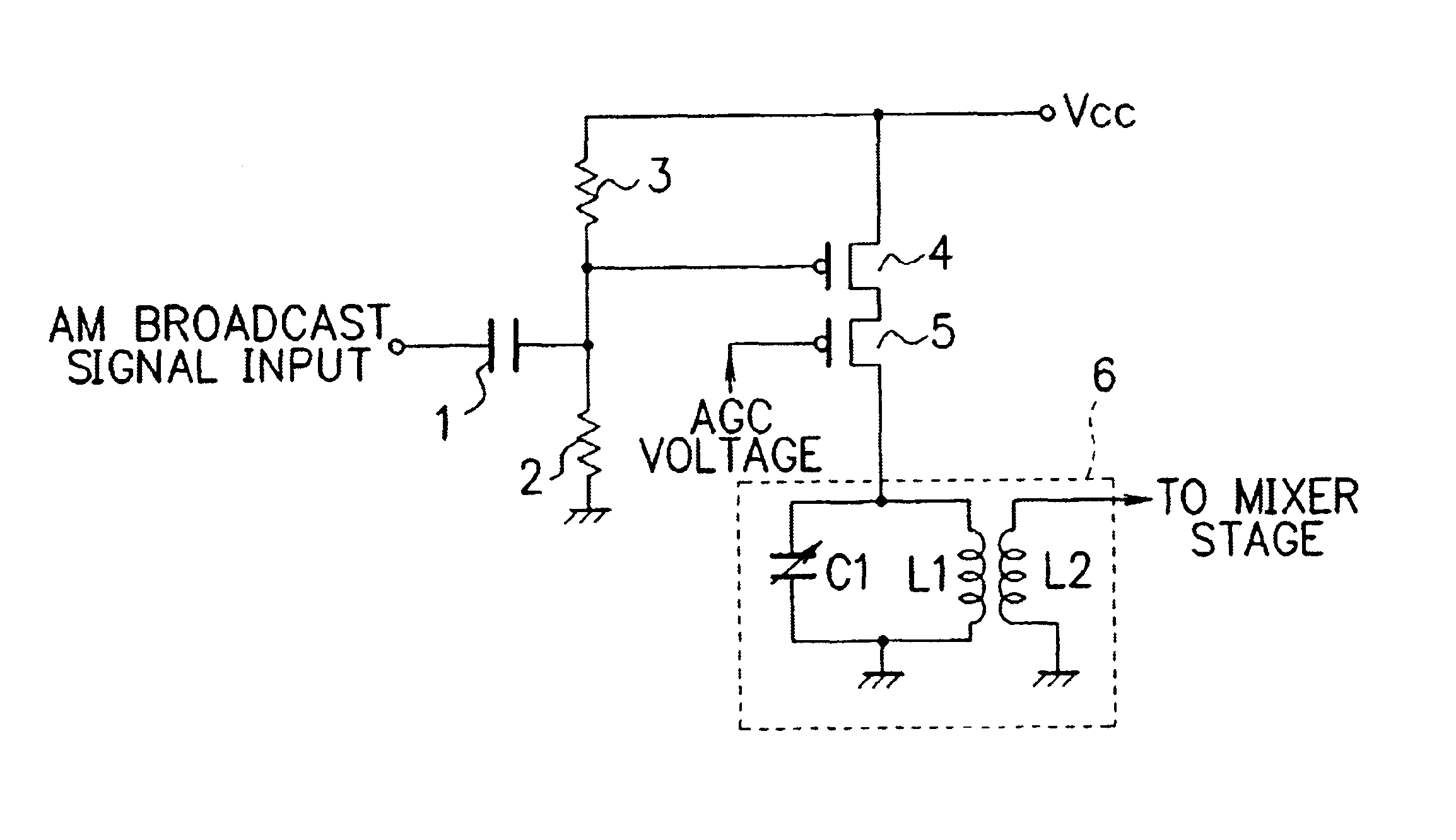
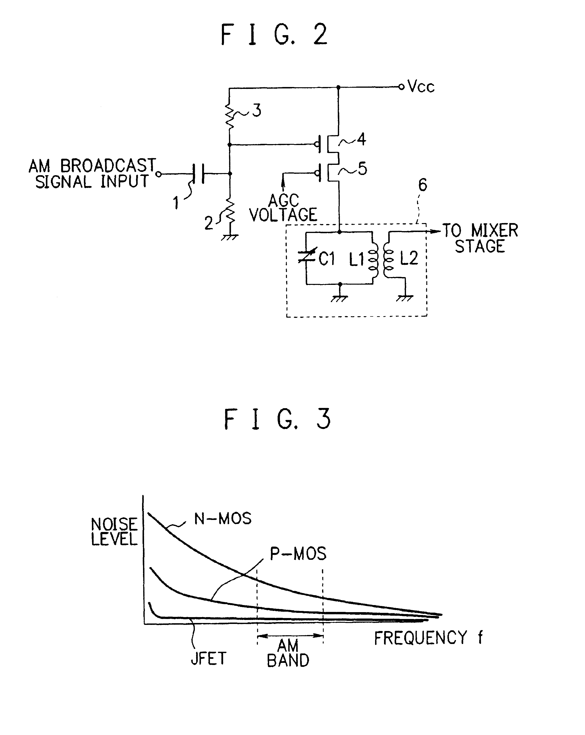
[0020]According to the present invention configured as shown above, an RF amplifier for AM broadcasting is constructed even in a low frequency area using P-channel MOSFETs which involves smaller flicker noise than N-channel MOSFETs, making it possible to integrate more circuits including the RF amplifier for AM broadcasting on one chip with a MOS structure while suppressing the flicker noise to a lowest possible level and thereby realize small size and low noise of the circuits.
[0021]Furthermore, according to another feature of the present invention, the channel area of P-channel MOSFETs is increased, which suppresses the flicker noise to a further smaller level.

Problems solved by technology

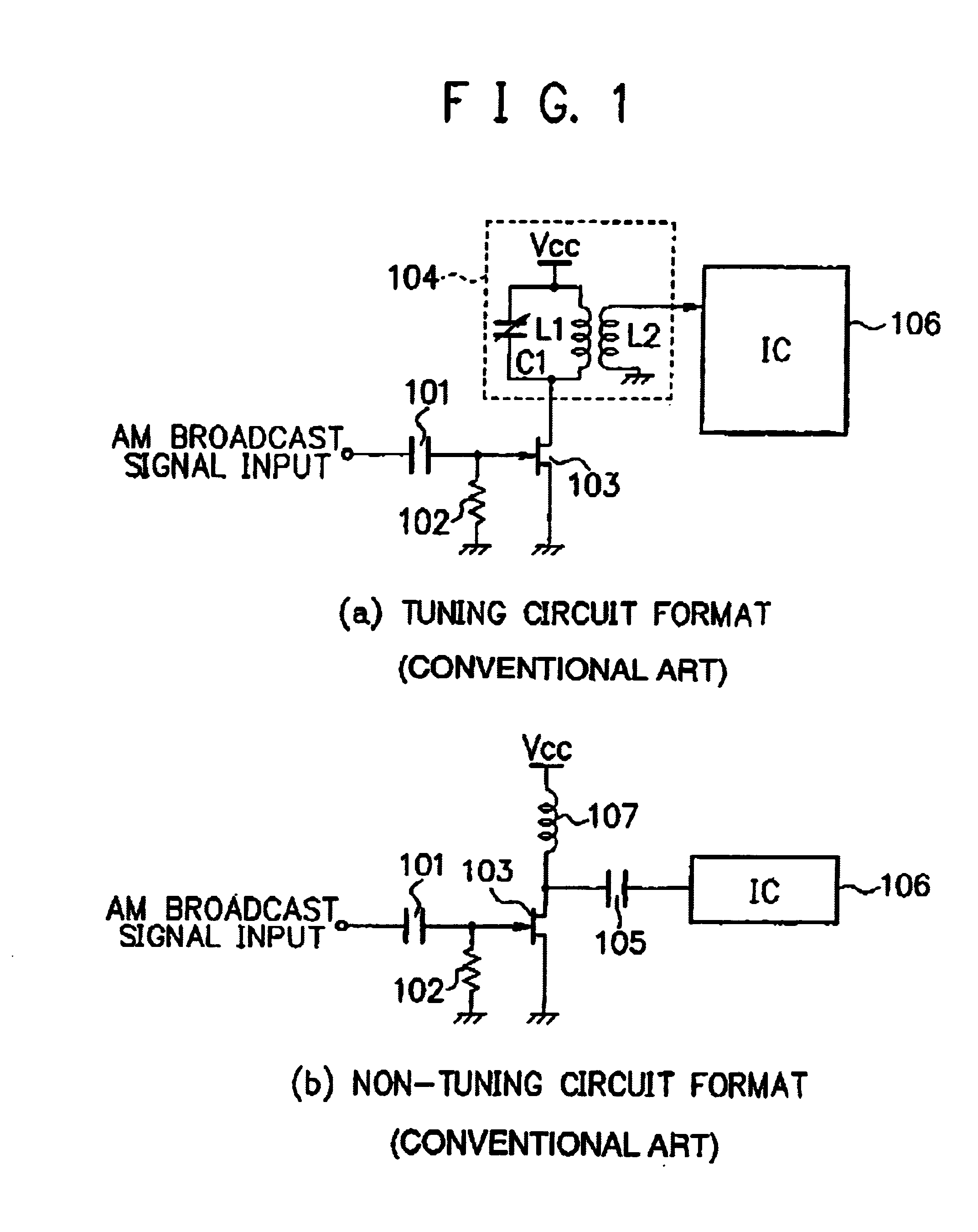
However, in the case of an AM broadcasting receiver handling low frequency signals of medium frequency such as 530 to 1710 KHz or low frequency such as 153 to 279 KHz, their frequency bands still belong to areas with large flicker noise components, and therefore it is not desirable to construct an RF amplifier with a CMOS circuit.
However, these conventional technologies are unable to integrate an RF amplifier together with another RF circuit, etc., on a single chip, and as a result, the conventional technologies have a problem that it is not possible to reduce the size of an entire circuit as in the case of a high frequency wireless terminal.

Method used


Image

  • Amplifier circuit for AM broadcasting
  • Amplifier circuit for AM broadcasting
  • Amplifier circuit for AM broadcasting

Examples


Embodiment Construction

[0025]With reference now to the attached drawings, an embodiment of the present invention will be explained below.

[0026]FIG. 2 shows a configuration of an amplifier circuit for AM broadcasting according to this embodiment. As shown in FIG. 2, the amplifier circuit for AM broadcasting of this embodiment is constructed of a capacitor 1, resistors 2 and 3, a first P-channel MOSFET 4, a second P-channel MOSFET 5 and a tuning circuit 6.

[0027]Here, the capacitor 1 is intended to cut a DC component of an AM broadcast signal inputted from an antenna which is not shown. The resistors 2 and 3 are intended to give an appropriate bias to the first P-MOSFET 4, connected in series between a power supply Vcc and ground and the capacitor 1 is connected at an intermediate node thereof.

[0028]The first P-MOSFET 4 is intended to amplify the AM broadcast signal outputted from the capacitor 1. Its gate is connected to the capacitor 1 at the intermediate node between the resistors 2 and 3, its source is c...


PUM


Abstract

An amplifier circuit for AM broadcasting for amplifying an inputted AM broadcast signal by an FET and outputting it. The amplifier circuit comprises FETs for signal amplification which are P-channel MOSFETs (4, 5) of relatively small flicker noise. While suppressing the flicker noise to a lowest possible level, more circuits including the RF amplifier for AM broadcasting can be integrated on one chip, thereby realizing small size and low noise of the circuits.

Description

CROSS REFERENCE TO RELATED APPLICATIONS[0001]This Application is a Continuation of application Ser. No. 10 / 606,964 filed on Jun. 27, 2003, now U.S. Pat. No. 6,753,736. Ser. No. 10 / 606,964 is a Continuation of application PCT / JP01 / 11552 filed on Dec. 27, 2001. PCT / JP01 / 11552 claims priority for application 2000-400737 filed on Dec. 28, 2000 in Japan.BACKGROUND[0002]1. Field of the Invention[0003]The present invention relates to an amplifier circuit for AM broadcasting, and more particularly, to one preferably applicable to an RF (Radio Frequency) amplifier used for a broadcast signal input stage of a radio receiver that receives AM broadcast signals, etc.[0004]2. Description of the Related Art[0005]FIG. 1 shows a configuration of a conventional AM broadcasting reception circuit. FIG. 1A shows a configuration of a tuning circuit format and FIG. 1B shows a configuration of a non-tuning circuit format. As shown in FIG. 1A, the conventional AM broadcasting reception circuit in the tuning...

Claims


Application Information

Patent Timeline
Patent Type & Authority Patents(United States)
IPC IPC(8): H03F3/04H03F1/22H03F1/26H03F3/16H03F3/193H03F3/195H04B1/16
CPCH03F1/223H03F1/26H03F3/193H03F3/195H03F3/1935H03F2200/541H03F2200/324H03F2200/372
Inventor IKEDA, TAKESHIMIYAGI, HIROSHI
Owner RICOH KK
Learn More