Fuel cell stand-by energy supply system

a technology of energy supply system and fuel cell, which is applied in the integration of power network operation system, emergency power supply arrangement, emergency supply, etc., can solve the problems of increasing power failures of utilities, and achieve the effect of maximizing the use of auxiliary power availabl

Inactive Publication Date: 2000-02-22
H POWER ENTERPRISES OF CANADA
View PDF3 Cites 47 Cited by
  • Summary
  • Abstract
  • Description
  • Claims
  • Application Information

AI Technical Summary

Benefits of technology

It is a feature of the present invention to provide a fuel cell stand-by energy supply system for supplying electrical power to one or more electrically operated devices in the event of a power failure and wherein the load of the device(s) is controlled and managed by a microcontroller in relation to the fuel cell power availability so as to maximize the use of the auxiliary power available by such fuel cells.
Another feature of the present invention is to provide a fuel cell stand-by energy supply system incorporating a microcontroller capable of minimizing the power consumption of a blower motor of a forced air furnace which is supplied by a fuel cell incorporated in a voltage conditioning circuit which produces an operative a.c. supply for the blower motor.
According to the above features, from a broad aspect, the present invention provides a fuel cell stand-by energy supply system for supplying electrical power to a device operated by power from an electrical utility in the event of a power failure. The stand-by energy supply system comprises detection means for detecting a power failure. Control circuit means is provided for monitoring the detection means and one or more conditions of the device. The control circuit means operates a fuel cell switch to connect a fuel cell or an integration fuel cell and battery d.c. supply directly or to a voltage conditioning circuit to produce an operative a.c. supply and for connecting the a.c. supply to the device to continue operation thereof during the power failure. The control circuit means also has power sensing means and means to control the operation of the device so as to maximize the use of the power available in the fuel cell.

Problems solved by technology

In recent years we have also found an increase in power failures by the utilities, this being due to line overloading, inclement weather conditions or for many other reasons.
We have also experienced power outages which have lasted many days and imposed hardships on thousands of households and which has led to some casualties.

Method used


Image

  • Fuel cell stand-by energy supply system
  • Fuel cell stand-by energy supply system
  • Fuel cell stand-by energy supply system

Examples


Embodiment Construction

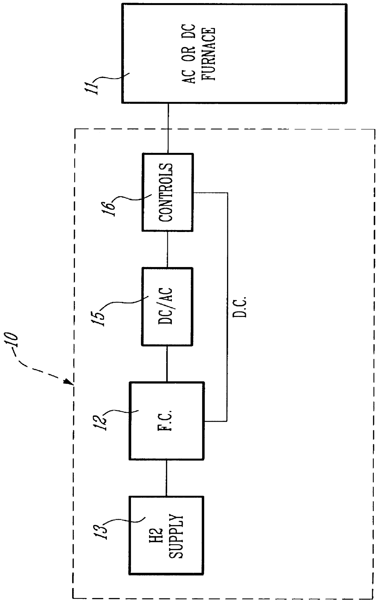
Referring now to the drawings, and more particularly to FIG. 1, there is shown one application of the fuel cell stand-by energy supply system 10 of the present invention and herein for supplying power to an electrically operated fossil fueled forced air furnace 11 in the event of a power failure by the utility. Essentially, the fuel cell stand-by energy supply system 10 is comprised of a fuel cell 12 which is hydrogen operated and fed hydrogen from a storage, cartridge or any other hydrogen supply source 13. The fuel cell stand-by energy supply system 10 incorporates a d.c. to a.c. converter circuit herein referred to as a voltage conditioning circuit 15 whereby to convert the d.c. supply from the fuel cell to an a.c. supply. A microcontroller 16 controls the stand-by energy supply system and provides various features such as the control and management of the load in relation to the fuel cell power, herein the forced air furnace 11 or other devices which may be connected to the supp...


PUM

PropertyMeasurementUnit
voltageaaaaaaaaaa
speedaaaaaaaaaa
temperatureaaaaaaaaaa

Abstract

A fuel cell stand-by energy supply system is provided for supplying electrical power to a device operated by power from an electrical utility in the event of a power failure. The system is comprised of a microcontroller which is connected to a detector capable of detecting power failure. The microcontroller monitors this detector and one or more conditions of the device to which electrical power is fed. The microcontroller operates a fuel cell switch to connect the fuel cell d.c. supply directly to the d.c. device or to a voltage conditioning circuit to produce an operative a.c. supply which is connected to the device to continue operation thereof during the power failure. The microcontroller monitors and manages the load in relation to the fuel cell power. The microcontroller also performs an autodiagnostic of the fuel cell.

Description

The present invention relates to a fuel cell stand-by energy supply system for supplying electrical power to a device, for example a fossil fuel forced air furnace, in the event of a power failure.Fuel cells are known as an alternate source of d.c. supply. The development of fuel cells has evolved greatly in the last decade and wherein these cells are now much more compact and less costly than heretofore. Fuel cells can now be powered by small cartridges in which hydrogen is stored under pressure. There are other means also available to power fuel cells.In recent years we have also found an increase in power failures by the utilities, this being due to line overloading, inclement weather conditions or for many other reasons. We have also experienced power outages which have lasted many days and imposed hardships on thousands of households and which has led to some casualties. There is therefore a need to provide an electrical stand-by system which is capable of operating at least th...

Claims


Application Information

Patent Timeline
Patent Type & Authority Patents(United States)
IPC IPC(8): H02J9/06H01M8/04
CPCH02J9/062Y02B90/14Y02B70/30Y02B90/10Y04S20/20
Inventor CHOUINARD, JEAN-GUYROBERGE, RAYMONDROSS, GUY
Owner H POWER ENTERPRISES OF CANADA
Why Eureka
Try Eureka