Friction clutch with wear compensation

Inactive Publication Date: 2000-02-29
MANNESMANN SACHS AG
View PDF9 Cites 9 Cited by
  • Summary
  • Abstract
  • Description
  • Claims
  • Application Information

AI Technical Summary

Benefits of technology

The spring which is fastened to the pressure plate holds the adjustment rings in position, these adjustment rings being tensioned relative to one another, when the clutch is released and the spring exerting the contact pressing force relieves the adjustment rings. When wear occurs at the friction facings and the pressure plate consequently wanders in the direction of the flywheel, the feeler which is contacted by the free end of the spring lifts the spring from the adjustment rings. At the same time, the feeler tilts in the pressure plate so that the rings can rotate relative to one another during the subsequent release movement because of their pretensioning and compensate for the play brought about by wear.
A particularly simple construction of the feeler is achieved by a pin and a lever which is fastened thereto and projects radially inward. The radial inner end of the lever is preferably angled axially in the direction of the housing, so that a good contact location is provided for the spring fastened to the pressure plate. The feeler can contact the flywheel or the housing. The feeler can be guided in a bore hole in the pressure plate or on a pin that is fixedly connected with the pressure plate.

Problems solved by technology

It is disadvantageous that the tilting must be configured for the least favorable operating state, so that it is safely ensured, for example, at high rates of rotation or high axial accelerations.
A failure of the tilting leads to an unwanted displacement of the compensation device or to failure of the clutch.

Method used


Image

  • Friction clutch with wear compensation
  • Friction clutch with wear compensation
  • Friction clutch with wear compensation

Examples


Embodiment Construction

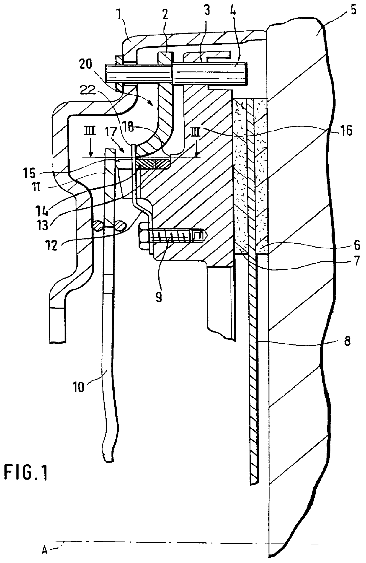
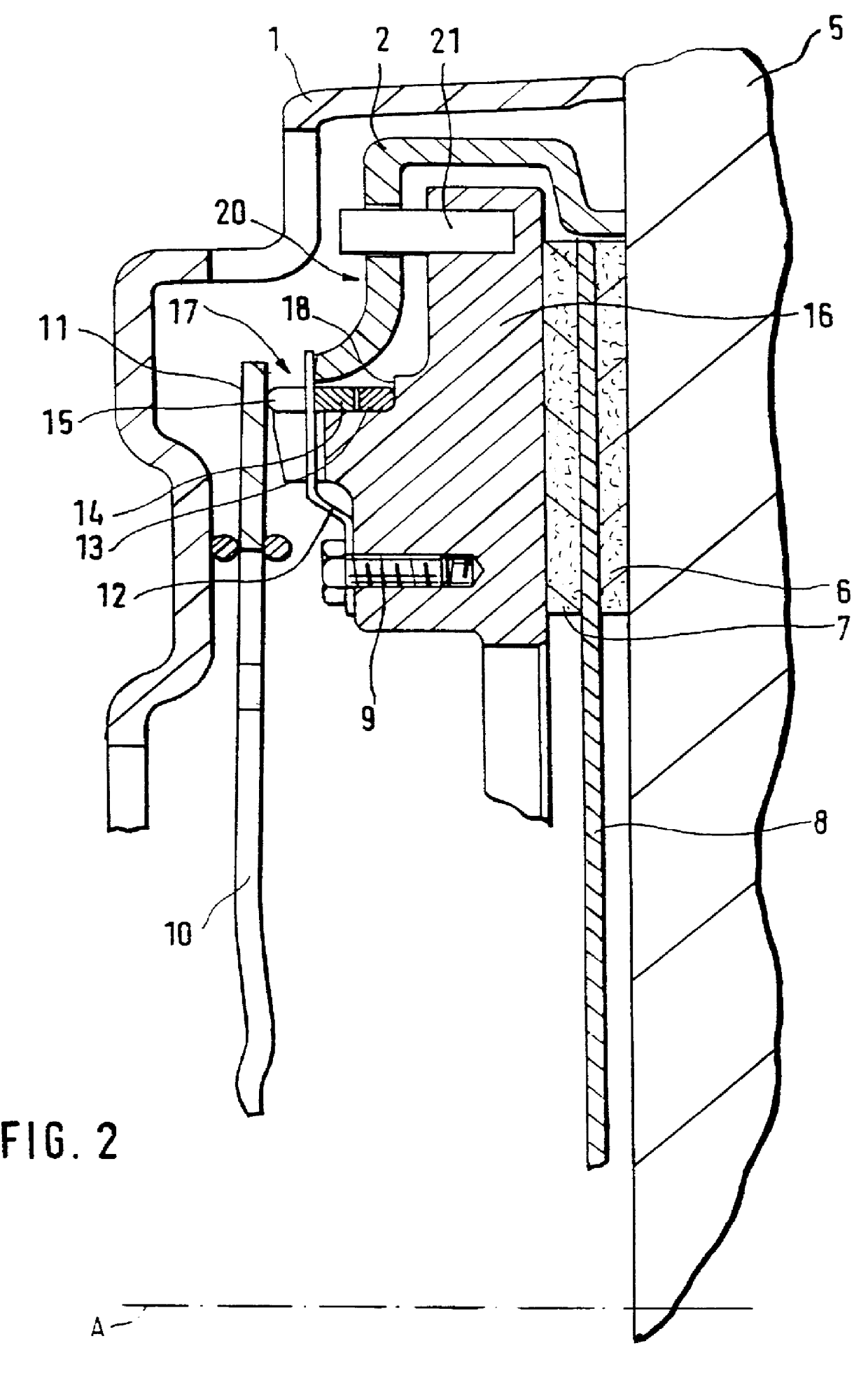
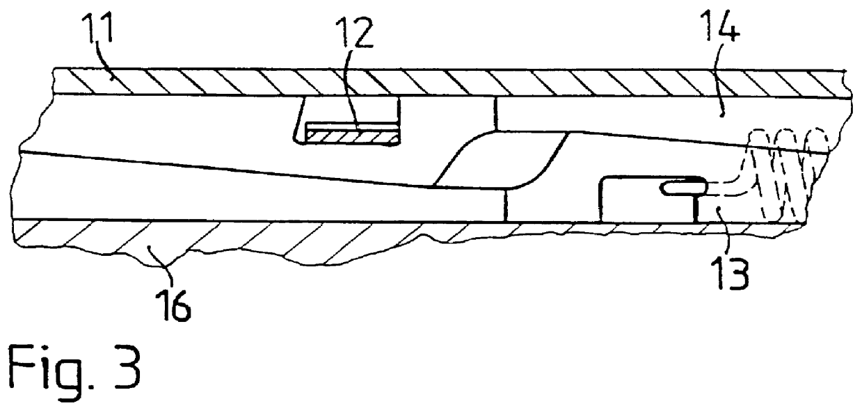
The friction clutch comprises a housing 1 which is connected with a flywheel 5 of an internal combustion engine, not shown in more detail, such that is it fixed with respect to rotation relative to the flywheel 5 and rotates about the axis of rotation A. A pressure plate 16 which is acted upon by a diaphragm spring 10 is arranged in the housing 1 and presses a clutch disk 8 provided with friction facings 6, 7 against the flywheel 5. Adjustment rings 13, 14 are arranged in an axial recess 18 in the pressure plate 16 and are pretensioned relative to one another and rotatable relative to one another in the circumferential direction by means of at least one spring, not shown. The contact pressing force applied by the diaphragm spring 10 acts with its free end 11 on the pressure plate 16 via the adjustment rings. A spring 12 is fastened by a screw 9 to the pressure plate 16 and extends radially outward at its free end 22. In the area of its free end 22, the spring 12 fits in a recess 15 ...


PUM


Abstract

A friction clutch having a housing which is connectable with a flywheel of an internal combustion engine so as to be fixed with respect to rotation relative to the flywheel. A pressure plate is arranged in the housing and is acted upon by a spring for pressing a clutch disk provided with friction facings against the flywheel. A compensation device, that includes at least one element which is changeable along its axial dimension, serves to compensate for the change in position of the pressure plate brought about by wear of the friction facings. A feeler is arranged so that it cannot change position relative to the pressure plate. The contact pressing force of the spring acts on the pressure plate via the compensation device. The feeler is arranged in the housing and a spring, which is fastened to the pressure plate and exerts an axial force on the compensation device, contacts the feeler at its free end.

Description

BACKGROUND OF THE INVENTION1. Field of the InventionThe present invention relates to a friction clutch, especially for motor vehicles, and more particularly to a friction clutch having a housing that is connectable with a flywheel of an internal combustion engine so as to be fixed with respect to rotation relative to the flywheel, a pressure plate which is arranged in the housing and is acted upon by a spring for pressing a clutch disk provided with friction facings against the flywheel, and a device that comprises at least one element which is changeable along its axial dimensions. The device serves to compensate for the change in position of the pressure plate brought about by wear of the friction facings. A feeler is arranged so that it cannot change position, wherein the contact pressing force of the spring acts on the pressure plate via the compensation device.2. Discussion of the Prior ArtA friction clutch of the type mentioned above is known, for example, from German referenc...

Claims


Application Information

Patent Timeline
IPC IPC(8): F16D13/58F16D13/75
CPCF16D13/757
Inventor WEIDINGER, REINHOLDWEISS, MICHAEL
Owner MANNESMANN SACHS AG
Why Eureka
Try Eureka