Resistance rail welding device with alignment mechanism

a technology of resistance rail and alignment mechanism, which is applied in the direction of rail joints, manufacturing tools, and ways. it can solve the problems of generating a moment of force which acts on the frame, the head of the finished continuous rail may not have a level running surface, and the risk of short-circuiting becomes particularly imminen

Inactive Publication Date: 2000-02-29
ESAB AB
View PDF12 Cites 17 Cited by
  • Summary
  • Abstract
  • Description
  • Claims
  • Application Information

AI Technical Summary

Problems solved by technology

One problem found in the use of a device of the above-mentioned kind for welding together for example a number of separate rails to form one long continuous rail is to ensure that each welding joint between two adjoining rails possesses a sufficiently high breaking strength and that each rail is securely welded in such a position that the upper part of the continuous rail thus formed, i.e. the so called rail head, is given a smooth running surface along its upper face and external flank, the so called track-forming edges, on which the railroad car wheels travel.
The rail flanks and / or the upper surfaces are not either manufactured to such a precision as to be completely straight, with the result that also when the work piece clamping members are positioned in parallel with one another a level running surface may not be obtained on the head of the finished continuous rail.
Since the short-circuiting risks increase the larger the surface of contact between the transverse end faces, the risk of short-circuiting consequently becomes particularly imminent in the case of rails wherein the end faces are completely parallel.
Another problem found in several of the welding devices used today, such as flash welding machines, is the use of a press element in the form of one large pressure cylinder only, a so called upsetting cylinder, for the final pressing-together of the work pieces, such as rails, in which case molten and oxidised material is squeezed outwards from the facing ends of the work pieces while at the same time the material underneath which is heated to welding temperature, is welded together.
Since in this kind of welding devices lack of space makes it difficult to position this pressure cylinder in such a manner that its longitudinal axis, i.e. centre line, coincides with the longitudinal axes of the work pieces, this kind of upsetting cylinder generates a moment of force which acts on the frame.
A further problem found in prior art welding devices is that they do not offer any possibility of compensating for the kind of deformation of the welding joint formed during the welding operation that may be caused by the very pressing-together of the rail on account of the bending forces arising during this operation, which deformation may result in an unacceptable welding-together of the two work pieces, despite careful and accurate alignment of the work pieces prior to the welding-proper.

Method used


Image

  • Resistance rail welding device with alignment mechanism
  • Resistance rail welding device with alignment mechanism
  • Resistance rail welding device with alignment mechanism

Examples


Embodiment Construction

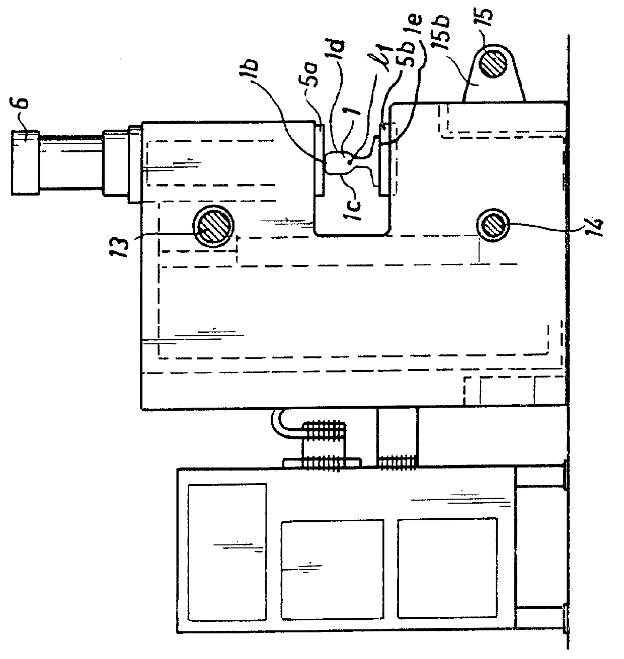
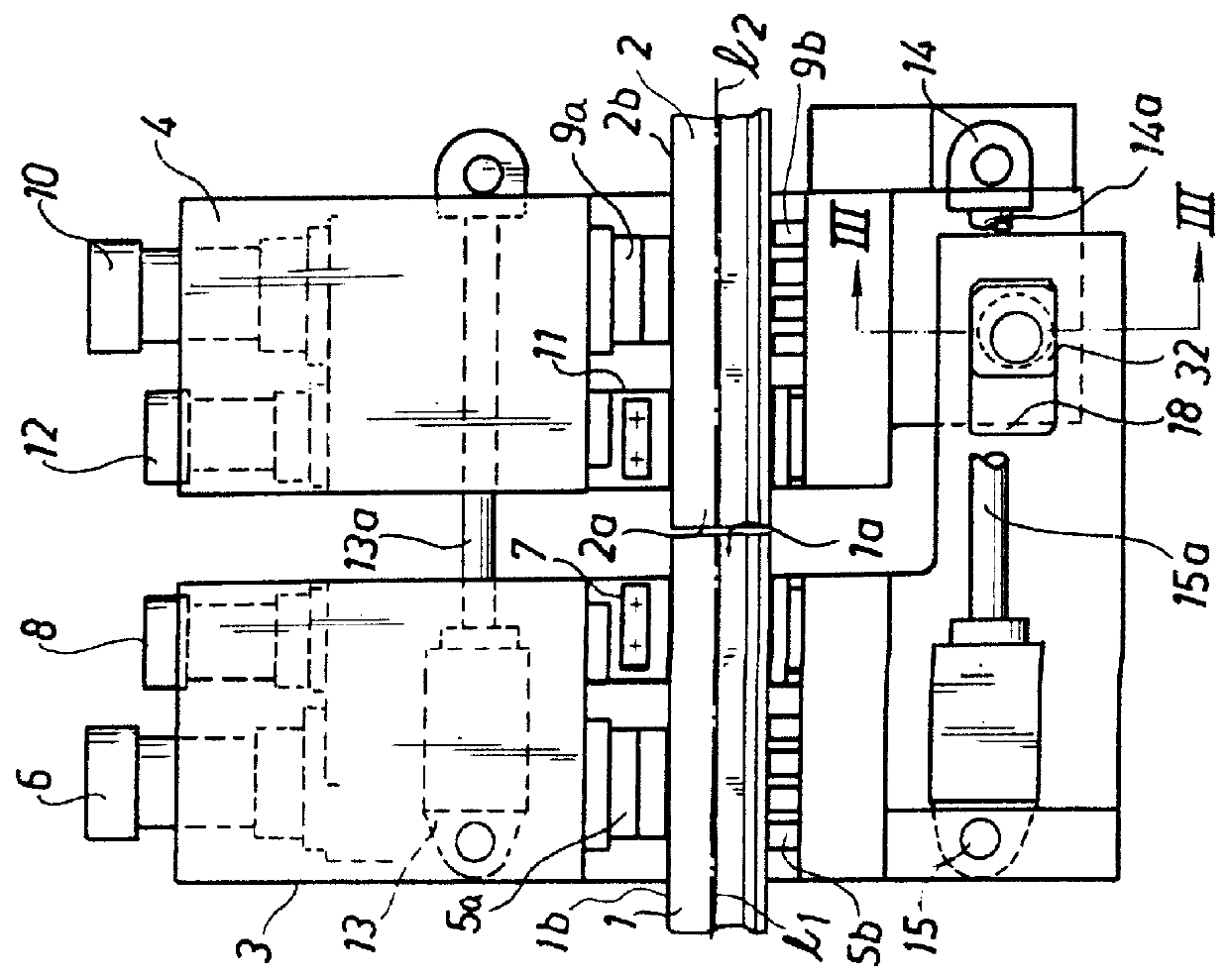
The welding device illustrated in FIG. 1 is intended to be used for welding together two rails 1, 2 at the front rail portions 1a and 2a by means of flash welding. By the front end portion is to be understood an area extending a distance of approximately 10-20 mm into the rails from the end face of the respective rail. The device consists of a stationary frame structure 3 and a carriage 4 movably connected thereto. The frame is provided with clamping dies 5a, 5b in the form of one lower and one upper die 5a and 5b, respectively, by means of which the rail 1 is secured in the frame 3. The dies are clamped about the rail by means of a cylinder 6. As appears from FIG. 2, the upper die abuts against the upper face 1b of the rail head and the lower die against the bottom face 1e of the rail. The frame is also provided with electrode dies 7 which are clamped about the rail 1 by means of a cylinder 8 adjacent the rail end portion 1a, to supply current for heating said end to the desired we...


PUM

PropertyMeasurementUnit
angleaaaaaaaaaa
angleaaaaaaaaaa
distanceaaaaaaaaaa

Abstract

PCT No. PCT/SE96/01597 Sec. 371 Date Jun. 5, 1998 Sec. 102(e) Date Jun. 5, 1998 PCT Filed Dec. 4, 1996 PCT Pub. No. WO97/21514 PCT Pub. Date Jun. 19, 1997A device for welding together elongated work pieces such as railroad track, is provided with controls to eliminate pre-existing angles that exist between each work piece prior to joining.

Description

1. Field of the InventionThe present invention relates to a device for welding together a first elongate work piece, such as a first rail, with a second elongate work piece, such as a second rail, end to end, by means of butt-weld resistance welding, particularly flash welding. The device comprises a structure and a carriage movably connected to the frame structure and slidable with respect thereto in the longitudinal direction of the work pieces, a first clamping device mounted on the frame structure or on parts associated therewith to fixedly clamp the first work piece, a second clamping device mounted on the carriage to fixedly clamp the second work piece, electrodes mounted on the frame structure and the carriage or on the clamping devices to heat the work pieces to the desired welding temperature, and a press element to press the facing ends of the heated work pieces against one another in the longitudinal direction of the work pieces to form a bonding welding joint.2. Discussi...

Claims


Application Information

Patent Timeline
Patent Type & Authority Patents(United States)
IPC IPC(8): B23K11/04E01B11/00E01B11/50
CPCB23K11/046E01B11/50B23K2201/26B23K2101/26
Inventor LARSSON, ROLF
Owner ESAB AB
Why Eureka
Try Eureka