

Spinning apparatus, method of producing yarns, and resulting yarns
a spinning apparatus and spinning machine technology, applied in the direction of yarn, drafting machines, continuous wounding machines, etc., can solve the problems of low yarn quality, slow ring spinning rate, fiber breakage, etc., to improve mechanical properties, increase strength, and high uniformity
Inactive Publication Date: 2000-03-14
WELLMAN INC
View PDF29 Cites 13 Cited by
- Summary
- Abstract
- Description
- Claims
- Application Information
AI Technical Summary
Benefits of technology
As described above, the spun yarn produced according to the invention has high uniformity and improved mechanical properties over conventional yarns produced according to conventional constructions having broader roll spacing. Specifically, the spun
Problems solved by technology
Although good quality natural yarns may be produced by ring spinning, the rate of ring spinning remains relatively slow, e.g., less than about 15 meters/minute.
Because adjacent pairs of rollers operate at different speeds, the bridged fibers may becom
Method used
View moreImage
Smart ImageViewing Examples

Examples
 PUM
| Property | Measurement | Unit |
|---|---|---|
| Length | aaaaa | aaaaa |
| Length | aaaaa | aaaaa |
| Force | aaaaa | aaaaa |
Abstract
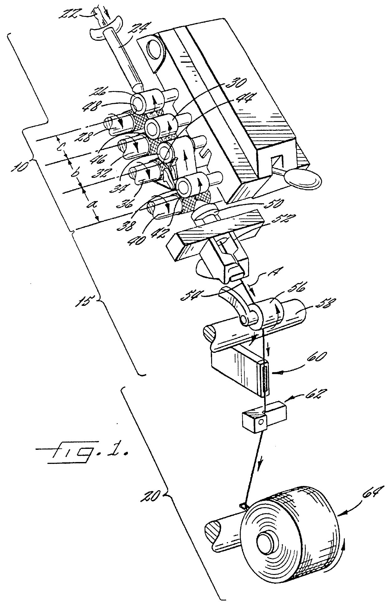
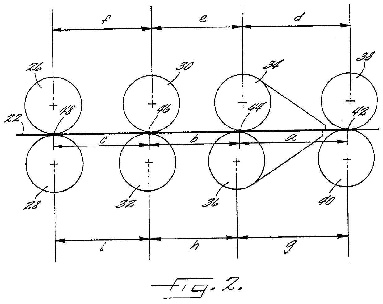
A spinning apparatus is disclosed according to the invention having a drafting zone comprising at least four roll pairs for drawing a sliver comprising one or more types of staple fibers. The rolls pairs include a back roll pair, intermediate roll pairs and a front roll pair and the distance between the nip of the back roll pair and the nip of the adjacent intermediate roll pair, and the distances between the nips of adjacent intermediate roll pairs is no more than the effective fiber length of the longest staple fiber type in the sliver. The drafted sliver may be spun into yarns at high speeds, such as the speeds used in air jet spinning apparatus to provide yarns having increased strength and reduced defects. The present invention also includes a method of forming high quality and high uniformity yarns by advancing a sliver through a drafting apparatus and thereafter spinning the sliver into yarn.
Description
The present invention relates to yarn spinning and more particularly, relates to a novel method of drafting sliver in a spinning apparatus to form highly uniform yarns having good mechanical properties.One common method of forming single yarns has been the use of a spinning apparatus which drafts and twists prepared strands of fibers to form the desired yarn. One of the first yarn spinning apparatus was the mule spinning frame which was developed in 1782 and used for wool and cotton fibers. Many decades later, the ring spinning apparatus was developed to increase the spinning speed and quality of the spun yarn. Although good quality natural yarns may be produced by ring spinning, the rate of ring spinning remains relatively slow, e.g., less than about 15 meters / minute. In the last few decades, other various types of spinning apparatus which operate at higher speeds than ring spinning apparatus have been introduced. For example, rotor spinning, friction spinning and air-jet spinning ...
Claims
Login to View More Application Information
Patent Timeline
 IPC IPC(8): D01H5/22D01H5/00D01H1/115D01H1/00D02G3/38D02G3/04D01H5/26
CPCD01H1/115D01H5/22D02G3/38D10B2201/02D10B2331/04
InventorSCHEERER, TODD JOSEPHMOORE, WINSTON PATRICKFLETCHER, JESSE ROBERTCREWS, RUDY LEE
OwnerWELLMAN INC