Fuel injection pump with an injection adjuster piston used to adjust the onset of injection

Inactive Publication Date: 2000-03-28
ROBERT BOSCH GMBH
View PDF4 Cites 5 Cited by
  • Summary
  • Abstract
  • Description
  • Claims
  • Application Information

AI Technical Summary

Benefits of technology

By means of the fuel injection pump of the invention, the advantage is attained that when relative displacements of the control slide occur, initially only a small cross-sectional area is opened, which for the same adjustment distance is smaller than the usual cross-sectional area established when the inlet cross section of the connecting line into the cylinder bore is circular. Thus, whenever because of relative motion between the injection adjuster piston and the control slide, the control slide is briefly adjusted out of its intrinsically correct position relative to the injection adjuster piston, only a very small throttling cross section is opened up, so that the mispositioning of the control slide is not immediately as a substantial change in pressure in the work chamber of the injection adjuster piston. This averts a fast, forceful reaction on the part of the injection adjuster piston to the brief mispositioning of the control slide in such a way that incorrect vibrating or oscillating positions of this kind cannot be amplified to cause further vibration or oscillation of the injection adjuster piston.Advantageous refinements of the embodiment of the inlet cross section of the connecting line into the cylinder bore are recited hereinafter. It is essential to attain a quasi-continuous course of the cross section with a steady adjustment of the control edge that controls this cross section; the increase in cross section is effected over a relatively long adjustment distance. In the open position, the full overflow cross section is then available, so that in an intentional adjustment of the control slide, a correction of the injection adjuster piston position can be made with the requisite speed.In a further advantageous feature, the adjustment of the control slide is effected in a manner known per se by means of an actuator, which in a part of the injection adjuster structurally connected to the housing encloses a pressure chamber with a surface acted upon by the control pressure. Because of this pressure chamber accommodated outside the injection adjuster piston, a decoupling of this pressure chamber from the pressure fluctuations in the work chamber of the injection adjuster piston is achieved, especially by means of the relief chamber located between the two. This provision as well, in a supplement to the embodiment defined herein, contributes to reducing pressure oscillations of the injection adjuster piston.Different exemplary embodiment of the invention are shown in the drawing and will be described in further detail below.FIG. 1 shows a section through a fuel injection pump of the distributor type with radially located pump pistons and a device for injection onset adjustment, in the embodiment according to the invention;FIG. 2 illustrates a cross section of an elliptical inlet;FIG. 3 illustrates a cross section of a parabolic inlet; andFIG. 4 illustrates a cross section of a hyperbolic inlet.

Problems solved by technology

In this kind of injection adjusting device, the problem arises that because of the load change in the cam drive of the fuel injection pump, pressure fluctuations occur in the region of the pressure chambers of the injection adjuster, or relative motions between the injection adjuster piston and the control slide.

Method used


Image

  • Fuel injection pump with an injection adjuster piston used to adjust the onset of injection
  • Fuel injection pump with an injection adjuster piston used to adjust the onset of injection
  • Fuel injection pump with an injection adjuster piston used to adjust the onset of injection

Examples


Embodiment Construction

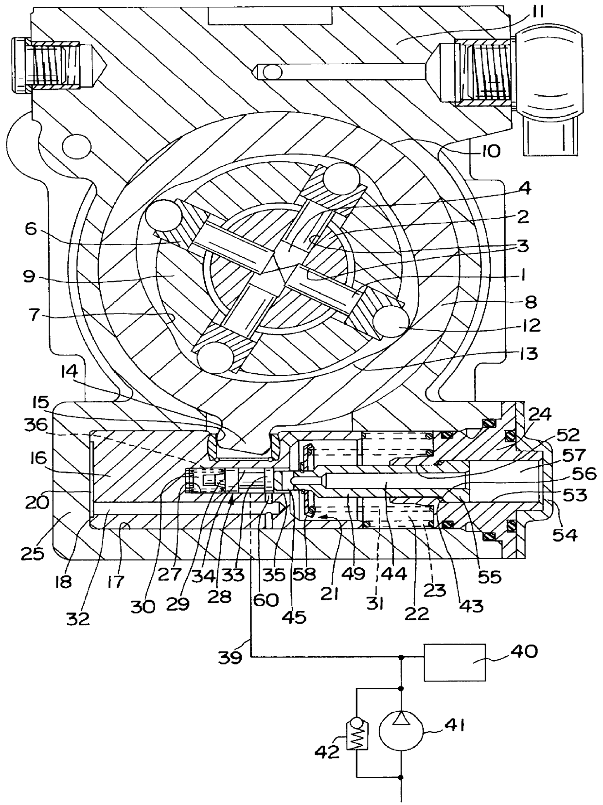
The fuel injection pumps of the distributor type may be provided with pumps either in the form of an axially driven pump piston acting as both a distributor and a pump piston, or with radial pistons which radially feed into a feed conduit disposed in a distributor. One such so-called radial piston pump of the known type is shown in section in FIG. 1. Four pump pistons 1 are provided, which are supported tightly displaceably in radial bores 3 of the distributor 2, at the same angular spacing in the same radial plane to the axis of the distributor 2. On one face end, the pump pistons enclose a common pump work chamber 4, which in a known manner, not shown in further detail here, is filled with fuel in the radially outward stroke of the pump pistons 1, and in the radial inward stroke of the pump pistons is made to communicate via a pressure line, also not visible here, with a distributor opening at the jacket face of the distributor 2; the distributor opening opens up injection lines t...


PUM


Abstract

PCT No. PCT / DE97 / 01225 Sec. 371 Date May 18, 1998 Sec. 102(e) Date May 18, 1998 PCT Filed Jun. 17, 1997 PCT Pub. No. WO98 / 14695 PCT Pub. Date Apr. 9, 1998A fuel injection pump for adjusting the injection onset by an injection adjuster piston. The piston is embodied as a follower piston of a control slide disposed in the piston on one side the piston encloses a work chamber and is acted upon by the pressure in this work chamber counter to the force of a restoring spring, and is connected to a substantially stationary part of a cam drive of the fuel injection pump. To avoid feedback of pressure surges on the control slide and its adjustment, the inlet cross section of the connecting line is embodied as an elongated cross section extending in the displacement direction of the control slide. A more problem-free adjustment of the control slide is thus obtained, and hence also a more-precise, vibration-free adjustment of the injection adjuster piston and of the injection onset is obtained.

Description

PRIOR ARTThe invention is based on a fuel injection pump including an injection adjuster piston used to adjust an onset of injection. In one such fuel injection pump, known from German Patent Disclosure DE-A1 35 32 715, an axially parallel blind bore that begins at the face end of the injection adjuster piston remote from the work chamber is provided as a connecting line between the work chamber and the cylinder bore; on its end, this blind bore is intersected by a transverse bore extending radially from the outside to the cylinder bore. The cross section of this transverse bore where it enters the cylinder bore has a circular area.In this kind of injection adjusting device, the problem arises that because of the load change in the cam drive of the fuel injection pump, pressure fluctuations occur in the region of the pressure chambers of the injection adjuster, or relative motions between the injection adjuster piston and the control slide.ADVANTAGES OF THE INVENTIONBy means of the ...

Claims


Application Information

Patent Timeline
IPC IPC(8): F02D1/00F02D1/18F02M41/08F02M41/14F02M41/12
CPCF02D1/183F02M41/128F02M41/1411F02D2001/186F02D1/18
Inventor FEHLMANN, WOLFGANGKULDER, THOMAS
Owner ROBERT BOSCH GMBH
Why Eureka
Try Eureka