Adjustable pitch impeller

a technology of impeller and pitch, applied in the field of impeller, can solve the problems of reducing efficiency, inability to provide a robust and reliable mechanism, and complex internal mechanism, so as to improve the control of blade rotation, strengthen the attachment, and improve the effect of control over the rotation of the blad

Inactive Publication Date: 2000-03-28
NEW FLUID TECH
View PDF18 Cites 51 Cited by
  • Summary
  • Abstract
  • Description
  • Claims
  • Application Information

AI Technical Summary

Benefits of technology

By having the blades on the spherical portion, and having the root of each blade of a configuration complementary to the shape of the spherical portion, the blades can be pivoted without producing an appreciable gap, or altering the gap at any point.
There is no requirement to manually adjust the hub portions, or to use an actuating means. In a simple form, the hub portions can be free to move relative to each other so that the pitch of the blades will be set according to the operating conditions of the impeller such as head pressure or the type of fluid. In this simple "free wheeling" alternative, the linking of the blades to both hub portions will minimise uneven forces or loads being applied to the impeller in use.

Problems solved by technology

This small gap allowed fluid to pass back through the impeller, which reduced its efficiency.
A disadvantage with known arrangements is that for fans or impellers having a large number of blades, the internal mechanism is extremely complicated, while for fans and impellers having a relatively smaller diameter, and therefore a small hub portion, it is generally not possible to provide a robust and reliable mechanism to vary the pitch of the blades.
These blades can pivot freely and at high speed rotation of the impeller, blade flutter or other undesirable vibrations can occur.

Method used


Image

  • Adjustable pitch impeller
  • Adjustable pitch impeller
  • Adjustable pitch impeller

Examples


Embodiment Construction

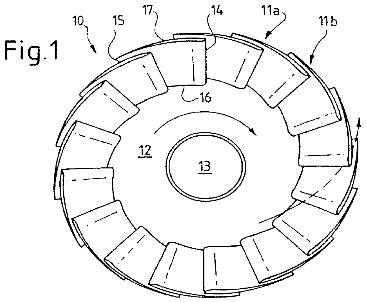
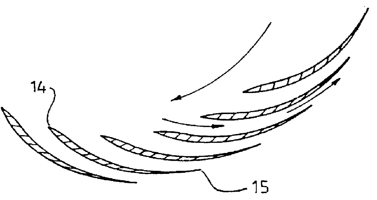
Referring to FIG. 1, there is illustrated an impeller 10. Impeller 10 comprises a plurality of blades 11a, 11b, etc., which extend about a hub 12. Hub 12 has a central axis of rotation 30 which is a bore passing through the hub so that the impeller can be press-fitted or otherwise mounted to a shaft. Each blade has a leading edge 14 and a trailing edge 15, a root portion 16 and a tip portion 17.

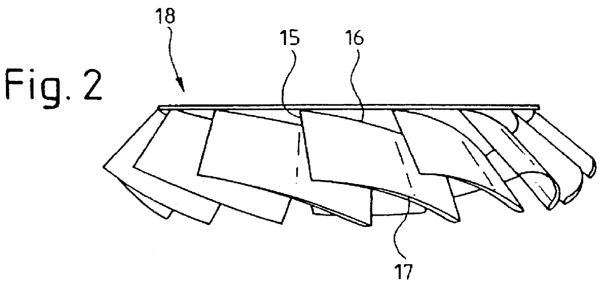
As shown in FIGS. 1-3, adjacent blades overlap each other such that when the impeller is caused to rotate, fluid passes between adjacent blades. The area between adjacent blades can be seen as a passageway through which the fluid passes. Each blade can have a thickened leading nose portion (see FIGS. 3 and 4) which functions to sweep fluid into the passageway defined between adjacent blades, and to reduce turbulence. However this may not be essential, and the leading edge can also be sharp. The impeller has a rear discharge area 18 which can be substantially flat. As fluid enters the passagew...


PUM


Abstract

An impeller has a plurality of rotating passageways which can be defined between adjacent blades, the blades having a curved root portion and able to pivot across a part spherical hub to maintain a fine line contact. The passageways have a convergence to improve the efficiency of the impeller. The hub can be split into two relatively rotating portions, with the blades attached to each portion to provide an efficient means to vary the pitch of the blades.

Description

TECHNICAL FIELDThis invention relates to an impeller and particularly relates to an improved impeller where the impeller hub has a spherical portion and where the impeller blades can be mounted to the hub in a manner which can improve the efficiency of the impeller. The invention also optionally includes an impeller having a split hub to allow the pitch of the impeller blades to be varied. The invention is applicable to impellers, but can also extend to other types of fan devices.BACKGROUND ARTIn certain applications of unducted and ducted fans and propellers, it is desirable to be able to adjust the pitch of the blades either between runs or during runs. This can be done by manual adjustment, or by allowing the blades to self-adjust during operation.Adjustment of fan or propeller blade pitch is known in the case of ordinary unducted fans and especially propellers. The mechanisms used to adjust the pitch are adequate as the propellers or fans are simply air movers and do not produce...

Claims


Application Information

Patent Timeline
Patent Type & Authority Patents(United States)
IPC IPC(8): F04D29/36F04D29/32
CPCF04D29/323F04D29/36
Inventor DAY, TERENCE ROBERT
Owner NEW FLUID TECH
Why Eureka
Try Eureka