Fluid displacement system

Inactive Publication Date: 2000-03-28
T D I THERMO DYNAMICS ISRAEL
View PDF17 Cites 54 Cited by
  • Summary
  • Abstract
  • Description
  • Claims
  • Application Information

AI Technical Summary

Problems solved by technology

However, heretofore prior art systems in the related field typically comprise mechanical or electromechanical components such as pumping means, valves etc, which require control means and an energy source and which in many cases are suitable only for liquids and are not suitable for handling gas or vapor or a combination of gas or vapor and liquid.
Furthermore, such mechanical components require periodical maintenance and replacing due to wear.
The drawbacks of this patent are t

Method used


Image

  • Fluid displacement system
  • Fluid displacement system
  • Fluid displacement system

Examples


Embodiment Construction

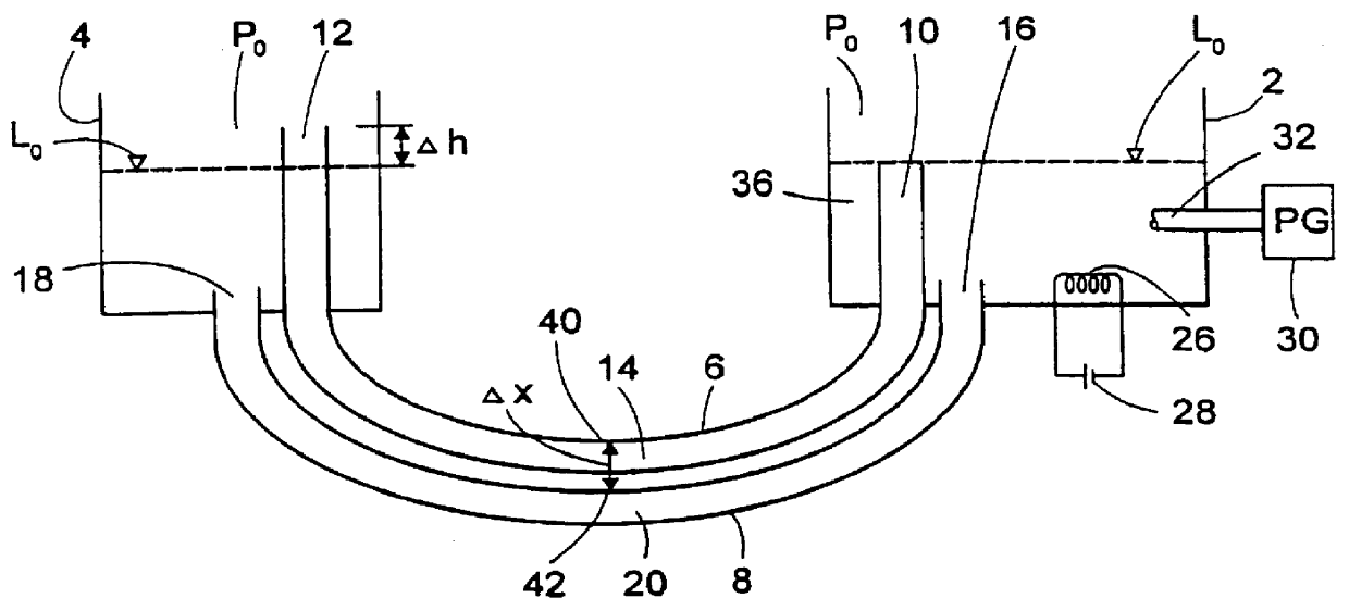
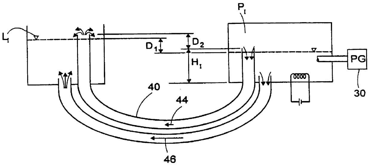
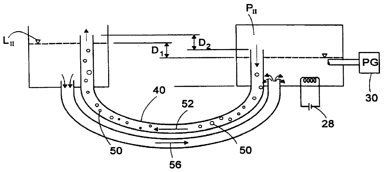
Attention is first directed to FIGS. 1(a) to 1(d) of the drawings for understanding the basic principles of the present invention, which as will be hereinafter explained, are applicable for all the applications and embodiments of the invention.

The system consists of a pressure vessel 2 and an expansion vessel 4, the vessels being connected to one another by a first tube 6 and a second tube 8, both tubes having an essentially U-like shape.

The first tube 6 has a first opening 10 within the pressure vessel 2 and a second opening 12 within the expansion vessel 4, with a lowermost portion 14 therebetween. The second tube 8 has a third opening 16 within the pressure vessel 2 and a fourth opening 18 within the expansion vessel 4, with a lowermost portion 20 therebetween. As can further be seen in the drawings, the first opening 10 is somewhat lower than the second opening 12 but extends at a noticeable height above the third and fourth openings 16 and 18 which extend adjacent the bottom po...


PUM


Abstract

In a fluid displacement system having a pressure vessel, an expansion vessel, first and second tubes in fluid communication with the two vessels, and an energy source, fluid contained within the system is transferred from one vessel to the other by activating the energy source, which in turn generates pressure in the pressure vessel. The generated pressure in the pressure vessel, in turn, displaces the fluid in the expansion vessel, and the system advantageously has no moving parts.

Description

The present invention is in the field of fluid displacement systems and more specifically it is concerned with a system useful as a cyclic fluid pulse generator. By another aspect of the invention, the system is useful also as a fluid flow rectifier.BACKGROUND OF THE INVENTION AND PRIOR ARTFluid displacement systems with which the present invention is concerned are at times referred to as "passive" or "self-pumping pump system", "geyser-type pump systems", "heat" or "thermal actuated pump systems" etc. However, heretofore prior art systems in the related field typically comprise mechanical or electromechanical components such as pumping means, valves etc, which require control means and an energy source and which in many cases are suitable only for liquids and are not suitable for handling gas or vapor or a combination of gas or vapor and liquid. Furthermore, such mechanical components require periodical maintenance and replacing due to wear.The following is a brief description of s...

Claims


Application Information

Patent Timeline
IPC IPC(8): F04B37/00F04B23/00F04B19/24F04B19/00F04B23/02F04B17/03F04B
CPCF04F1/04F04F1/06F04B23/02
Inventor ORIAN, ITAMAR
Owner T D I THERMO DYNAMICS ISRAEL
Why Eureka
Try Eureka