Gear pump

a gear pump and gear technology, applied in the direction of piston pumps, positive displacement liquid engines, liquid fuel engines, etc., can solve the problem of large size of the overall gear pump, and achieve the effect of compact overall size of the gear pump

Inactive Publication Date: 2000-04-11
KOYO SEIKO CO LTD
View PDF9 Cites 5 Cited by
  • Summary
  • Abstract
  • Description
  • Claims
  • Application Information

AI Technical Summary

Benefits of technology

The present invention has been made with the aim of solving the above problems, and it is one object of the present invention to provide a gear pump which is constituted of a pump housing formed cylindrically around the axis of a drive shaft which rotates a drive gear; and an eccentric structure of a gear chamber wherein a slave gear is disposed eccentric with respect to the axis of said drive shaft. An eccentric pitted portion being decentered with respect to the axis of said drive shafts deposed to the pump housing, whereby said eccentric pitted portion is used as a fluid returning for return fluid. As a result, the overall size of the gear pump can be compact without generating cavitation.

Problems solved by technology

In the gear pump constituted as described above, return fluid is directly returned to the low pressurized chamber F. Since the return fluid is returned to the low pressurized chamber F at a certain velocity, there has been a problem that an operating fluid contained in the low pressurized chamber F is agitated by the return fluid and thus air bubbles produced by the agitation are sucked into the gear chamber D, resulting cavitation.
However, it results in such a problem that the pump housing G, in its turn, the overall gear pump becomes large-sized, on the other hand.

Method used


Image

  • Gear pump
  • Gear pump
  • Gear pump

Examples


Embodiment Construction

The present invention will be described in detail herein after in conjunction with the accompanying drawings.

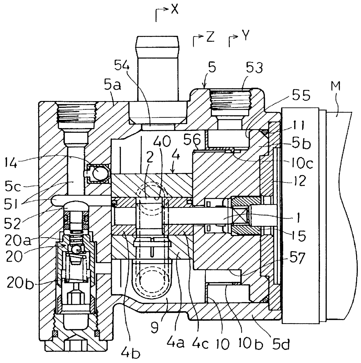
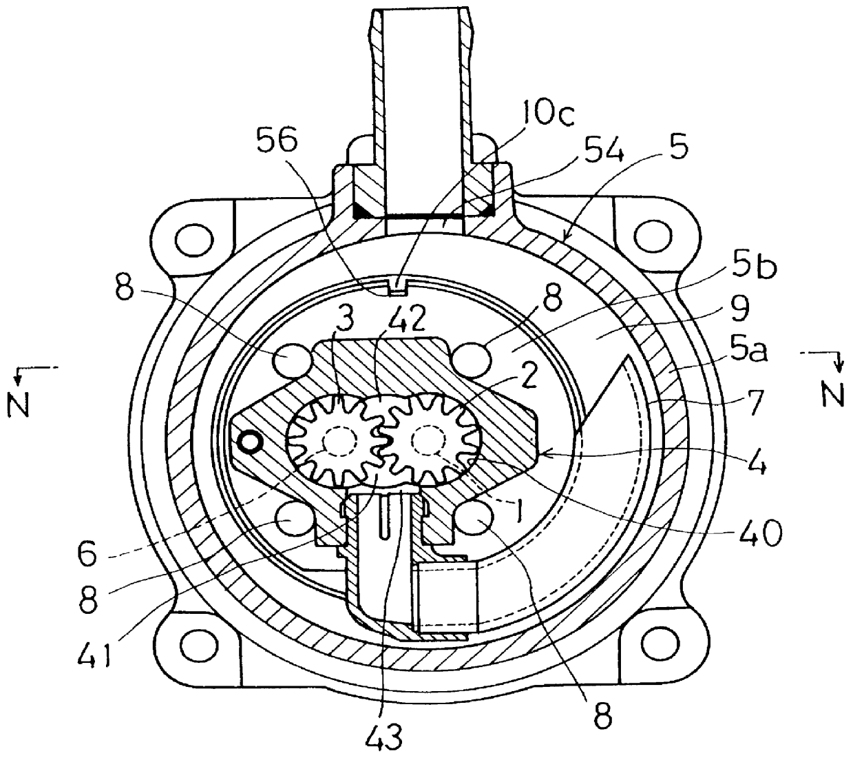
FIG. 2 is a front elevational view showing the gear pump according to the present invention, FIG. 3 is a sectional view taken along the line X--X of FIG. 2, FIG. 4 is a sectional view taken along the line Y--Y of FIG. 2, FIG. 5 is a sectional view taken along the line Z--Z of FIG. 2, and FIG. 6 is a sectional view taken along the line N--N of FIG. 3, respectively.

The gear pump shown in FIGS. 2 to 6, inclusive, is provided with a drive gear 2 rotated by an electric motor M provided next to the gear pump via a drive shaft 1; a slave gear 3 meshed with the drive gear 2; a gear housing 4 having a gear chamber 40 containing these drive and slave gears 2 and 3; and a pump housing 5 containing the gear housing 4 and rotatably supporting the drive shaft 1.

The gear housing 4 contains is provided with a cylindrical body portion 4a containing an elliptical gear chamber 40 communicating ...


PUM


Abstract

A gear pump is provided with a drive gear rotated via a drive shaft; a slave gear; a gear housing containing a gear chamber housing these gears therein; and a pump housing composed of a cylindrical housing main body with a bottom which contains the gear housing for serving as a low pressurized chamber, the inside of which communicates with the gear chamber, and an opening being defined thereon, and a covering member for closing the opening, wherein an eccentric pitted portion being eccentric with respect to the axis of the drive shaft is defined on the covering member, and the fluid return port is allowed to face to the eccentric pitted portion to function the eccentric pitted portion as a return fluid passage for return fluid, whereby it is possible to reduce a size of the gear pump without accompanying any cavitation.

Description

BACKGROUND OF THE INVENTIONThe present invention relates to a gear pump provided with a drive gear and a slave gear meshed with each other.A gear pump is described, for example, in Japanese Patent Publication No. 15592 / 1991 (Hei 3-15592) wherein this conventional gear pump is, as shown in FIG. 1, provided with a drive gear B rotating via a drive shaft A; a slave gear C meshed with the drive gear B; a gear housing E provided with a gear chamber D containing these drive and slave gears B and C; and a pump housing G containing the gear housing E and functioning as a low pressurized chamber F the inside of which communicates with said gear chamber D.The pump housing G is composed of a housing main body G1 defining an opening on one side of the housing in the axial direction of the drive shaft A and a detachable covering member G2 for closing the opening.A gear pump as described above is arranged in such that accumulated in the above described low pressurized chamber F is an operating fl...

Claims


Application Information

Patent Timeline
Patent Type & Authority Patents(United States)
IPC IPC(8): F04C11/00B62D5/07F04C2/18
CPCF04C11/008
Inventor HAMASAKI, YOSHIAKIIIDA, TOSHIO
Owner KOYO SEIKO CO LTD
Why Eureka
Try Eureka