Wideband acoustic transducer

a wideband acoustic transducer and waveguide technology, applied in the field of acoustic transducers, can solve the problems of reducing sensitivity, reducing pulse duration, and conflicting objectives

Inactive Publication Date: 2000-04-11
ARDENT SOUND
View PDF30 Cites 189 Cited by
  • Summary
  • Abstract
  • Description
  • Claims
  • Application Information

AI Technical Summary

Problems solved by technology

These objectives, however, typically conflict.
Measures taken to increase the bandwidth of the transducer tend to decrease the pulse duration but diminish the sensitivity.
Similarly, adjusting the configuration of a transducer to improve the sensitivity tends to diminish the bandwidth of the transducer.
In addition, the increased impedance of the backing may undesirably increase the pulse duration, as may be observed in FIG. 8B for backing impedances greater than about 6.5 MRayl.

Method used


Image

  • Wideband acoustic transducer
  • Wideband acoustic transducer
  • Wideband acoustic transducer

Examples


Embodiment Construction

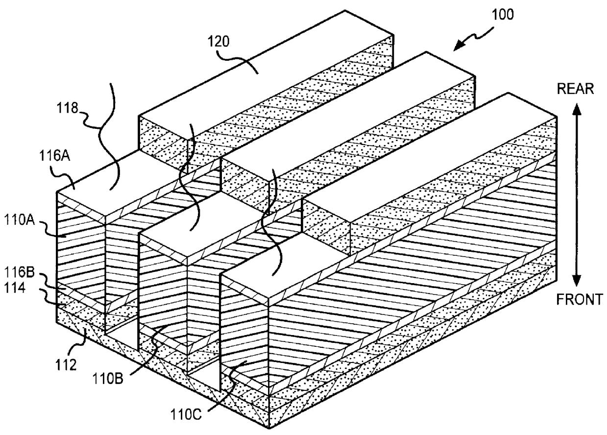
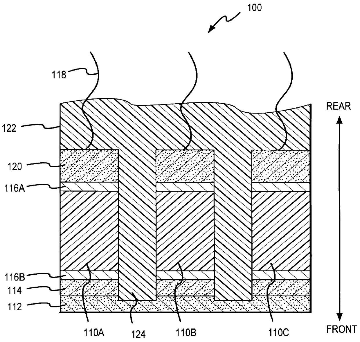
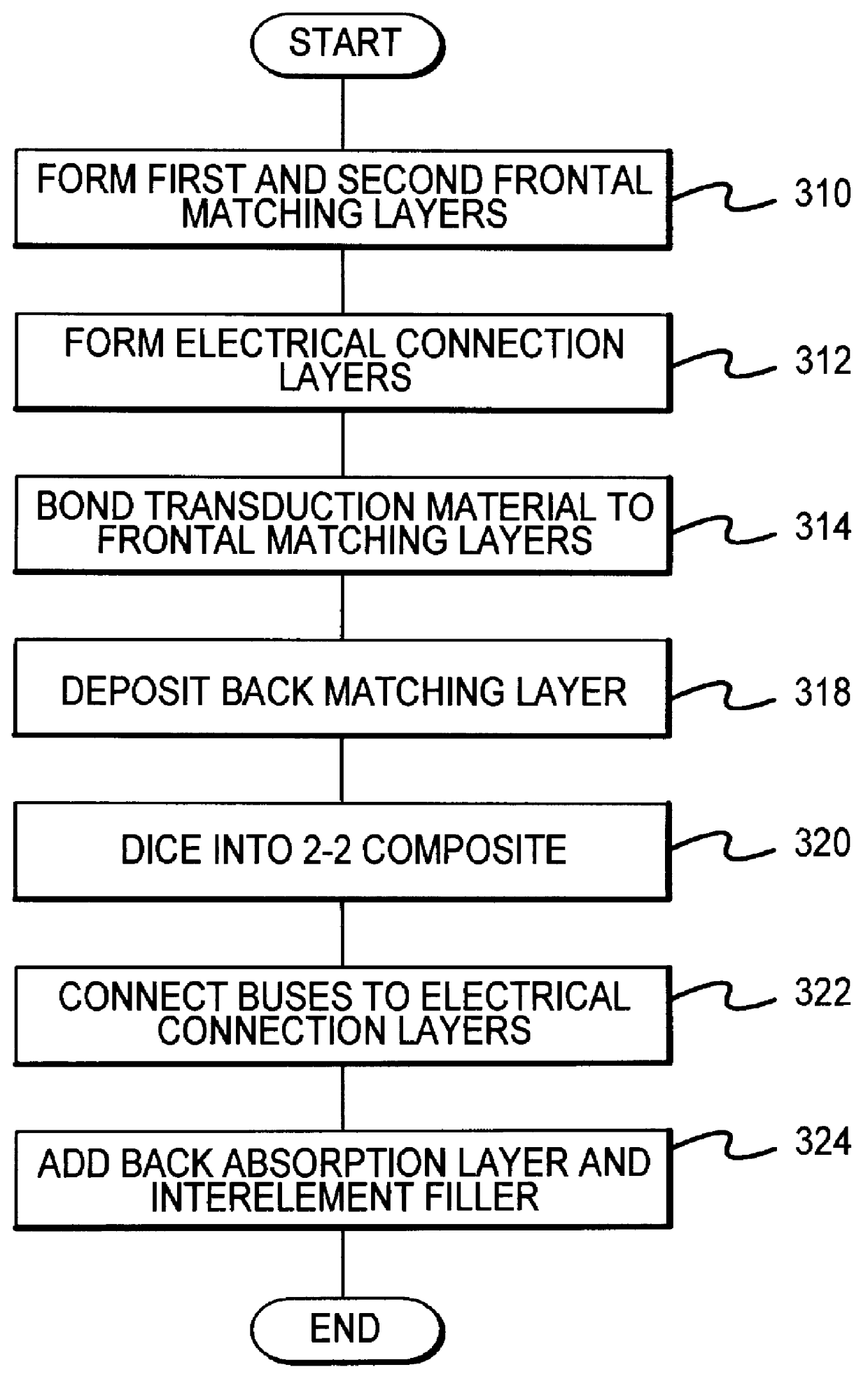
Referring now to FIGS. 1 and 2, an acoustic transducer 100 according to various aspects of the present invention comprises a transduction material 110; at least one frontal matching layer 112; a pair of electrical connection layers 116A-B; at least one electrical bus 118; a back matching layer 120; and a back absorption layer 122. Additional components, such as additional frontal matching layers, a physical interface, and the like, may be further included as described in greater detail below.

The transduction material 110 transforms one form of energy to another. For example, the transduction material 110 suitably transforms electrical energy into acoustic energy and vice versa. In the present embodiment, the transduction material 110 comprises any suitable piezoelectric material, such as piezoelectric ceramics, piezoelectric crystals, piezoelectric plastics, or piezoelectric composite materials, including lithium niobate, lead zirconate titanate, lead titanate, barium titanate, or l...


PUM


Abstract

A transducer according to various aspects of the present invention provides high fractional bandwidth with relatively low degradation of the pulse duration and sensitivity. The transducer includes a back matching layer behind the transducer material. The back matching layer is characterized by an impedance selected to transmit a selected portion of the backwards propagating acoustic energy to an absorption layer. The remaining acoustic energy is reflected in the desired direction of propagation. As a result, the transducer provides enhanced bandwidth without excessive loss of sensitivity or increase in pulse duration.

Description

1. Field of the InventionThe invention relates to acoustic transducers, and more particularly, to ultrasonic acoustic transducers having high bandwidth and sensitivity.2. Description of the Related ArtSince the latter portion of the twentieth century, ultrasonics has developed into an important field for a wide array of applications, such as detecting flaws in engineering, imaging in medicine, and signaling in marine environments. In particular, ultrasound is widely used in the detection of objects in a medium, such as finding the floor of the ocean or underground pipes. Similarly, ultrasound may be used to identify flaws and cracks in a structure.One of the most well known applications is medical imaging for fetal evaluation, disease detection and identification, and evaluation of internal organs and structures. Ultrasound may also be used to explore characteristics of tumors and cysts that are not disclosed by conventional imaging techniques, such as conventional X-rays. Ultrasoni...

Claims


Application Information

Patent Timeline
Patent Type & Authority Patents(United States)
IPC IPC(8): B06B1/06G10K11/02G10K11/00
CPCG10K11/02B06B1/0681
Inventor BARTHE, PETER G.SLAYTON, MICHAEL H.
Owner ARDENT SOUND
Why Eureka
Try Eureka