Suitcase with variable capacity

a technology of case and capacity, applied in the field of case with variable capacity, can solve the problems of affecting the stability of the case, high cost of purchasing several cases of different sizes, and considerable storage requirements

Inactive Publication Date: 2000-04-18
MP MICHAEL PFEIFFER DESIGN & MARKETING
View PDF24 Cites 48 Cited by
  • Summary
  • Abstract
  • Description
  • Claims
  • Application Information

AI Technical Summary

Benefits of technology

The shells have, advantageously, a circumferential edge which abuts an inner circumferential edge of the associated frame half and snaps in behind beads arranged parallel to the circumferential edge in the associated frame half. These snap-in beads secure the shells in their position of abutment. This type of connection makes it possible for the shells to be exchanged quickly and the case is thus easy to operate.

Problems solved by technology

The costs of purchasing several cases of different sizes is high and the storage requirements considerable.
Both solutions, however, have the disadvantage that the folds and the flexible intermediate part affect the stability of the case unfavourably.
The fold and the flexible intermediate part reduce the overall stability of the case.
Stresses from outside may cause the case to become deformed.
This could lead to damage to the case, itself, or to its contents.
Opening and closing the case places a great stress on the hinges.
When hinges are constructed as detachable connections, they normally produce a weak spot which reduces the service life of the case.
The shells consist of a resilient material which reduces the stability of the case.
When the shells are frequently exchanged it may occur that the above snap connection fails because of wear and tear of the material.
The dimensions of these projections are such that the buckle may be pulled over these projections by exerting some force, but that the natural weight of the buckle and of the shoulder strap is not sufficient to allow the buckle to drop down over the projection.

Method used


Image

  • Suitcase with variable capacity
  • Suitcase with variable capacity
  • Suitcase with variable capacity

Examples


Embodiment Construction

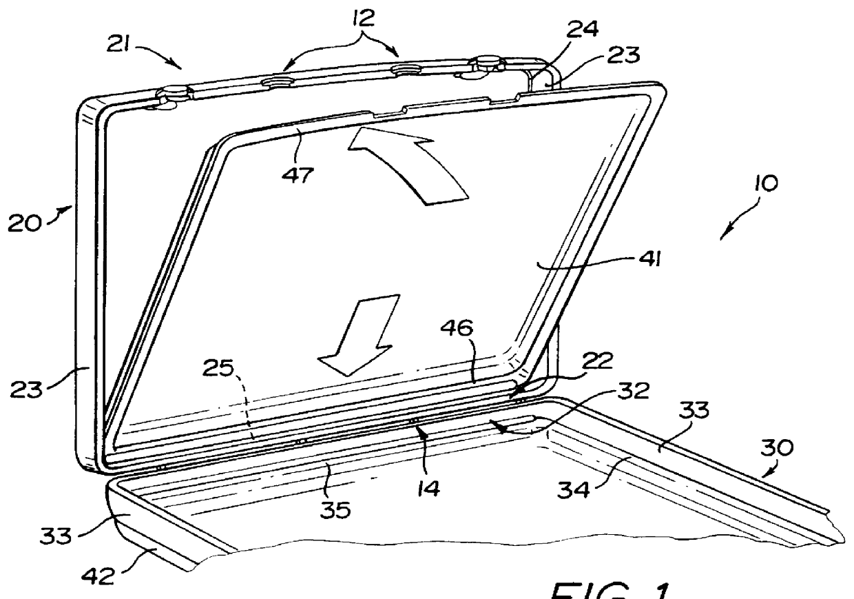
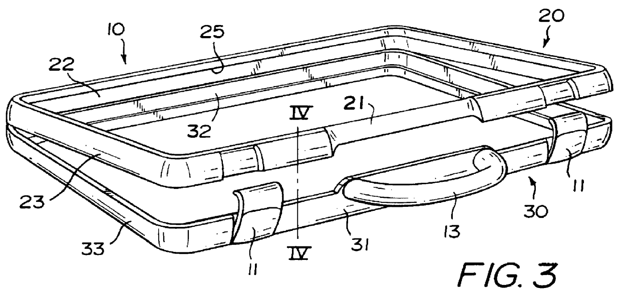
A central part 10 shown in FIGS. 1 and 3 is formed by two frame halves 20,30. Each frame half has a grip side 21,31, a hinge side 22,32 and two side parts 23,33. The two frame halves 20,30 are hinged to one another by hinges 14. On the sides of the frame half 20,30, which are positioned opposite the hinges 14, there are locking means 11. Between the locking means in the frame halves 20,30, there are recesses 12 for receiving a handle 13 (not shown in FIG. 1). The frame halves 20,30 each have a circumferential edge 24,34. Furthermore, there are grooves or beads 25, 35, 78 on the inside hinge side 22,32 of the frame halves 20,30, parallel to the hinges 14.

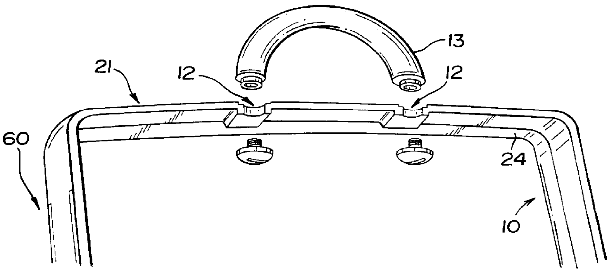
An advantageous construction of a handle 13 and a handle attachment without hinges in the central part 10 is shown in FIG. 2. Advantageously, the handle 13 is made of a tube-like, flexible material whose two ends are secured to the central part 10. The tube-like handle may contain a reinforced insert, for example a metal cable or a c...


PUM


Abstract

PCT No. PCT / EP95 / 02852 Sec. 371 Date Jan. 17, 1997 Sec. 102(e) Date Jan. 17, 1997 PCT Filed Jul. 19, 1995 PCT Pub. No. WO96 / 02160 PCT Pub. Date Feb. 1, 1996This invention relates to a case with a variable capacity, comprising a central part (10) which has two stable frame halves (20,30) hinged to one another which serve as supports for a single pair of various size sheet pairs (41,42;51,52) defining the interior of the case, the shells (41,42;51,52) being detachably connected to the frame halves (20,30) of the central part (10), so that shells of different depths may be used together with the same central part. The invention also relates to a set of cases, comprising a central part and two or several pairs of shells.

Description

This invention relates to a case with a variable capacity, comprising a central part which has two stable frame halves hinged to one another which serve as supports for a single shell pair forming the interior of the case.RELATED ARTIn conventional cases, for example suitcases or travel cases, the volume of the case interior is mostly constant. Therefore, for different volumes of clothes to be packed, different cases are required. For a business trip, for example, lasting only a few days, a smaller case is necessary than for a holiday lasting several weeks. The costs of purchasing several cases of different sizes is high and the storage requirements considerable.Various prior art cases are known, of which the inside volume is variable, so that a case is provided which is able to accommodate different quantities. A case is, for example, known from the German registered design GM 77 26 305 which may be enlarged gradually up to double the volume, as required. For this purpose, in parti...

Claims


Application Information

Patent Timeline
Patent Type & Authority Patents(United States)
IPC IPC(8): A45C13/26A45C13/00A45C7/00A45C5/03A45C5/00A45C5/02A45C7/02A45F3/02
CPCA45C5/03A45C13/26A45C7/005Y10S190/901A45F3/02A45C5/00
Inventor WONKA, JUSTINEPFEIFFER, FRANZISKAPFEIFFER, NICOLE
Owner MP MICHAEL PFEIFFER DESIGN & MARKETING
Why Eureka
Try Eureka