Method and apparatus for reducing system snoop latency

a technology of system snoop and latency, applied in the field of data processing systems, can solve the problems of system 100 configuration not achieving any increased performance over a system, affecting the overall performance of the system, and reducing the time required to snoop

Inactive Publication Date: 2000-04-18
GOOGLE LLC
View PDF16 Cites 9 Cited by
  • Summary
  • Abstract
  • Description
  • Claims
  • Application Information

AI Technical Summary

Benefits of technology

In one aspect, the present invention is an apparatus operating in a data processing system having a system bus, a memory controller, and an Input / Output (I / O) bus including at least one I / O cache. The processor is coupled to the system bus which is coupled to the memory controller, which in turn is coupled to the memory and the I / O bus. The apparatus is for reducing the time required to snoop address request for data residing in the at least one I / O cache.

Problems solved by technology

Specifically, these multi-processor systems have a number of bottlenecks that degrade their overall performance.
For instance, those; and skilled in the art are well aware of the difficulty of increasing processor performance due to the inability to keep the processors and their respective caches supplied with instructions and / or data.
Unfortunately, the design of system 100 results in a problem where the number of cycles required to snoop cached data in the BUCs (108 and 110) from an address placed on the system bus 112 to snoop response back to the system bus 112 is relatively long; especially when compared to the number of cycles required by one of the processors 102 or 104 to snoop its associated caches.
Further, if all addresses were required to be snooped down to the Mezzanine bus 116, then the system 100 configuration would not achieve any increased performance over a system using a combined system and Mezzanine bus.

Method used


Image

  • Method and apparatus for reducing system snoop latency
  • Method and apparatus for reducing system snoop latency
  • Method and apparatus for reducing system snoop latency

Examples


Embodiment Construction

In the following description, numerous specific details are set forth such as specific word or byte lengths, etc., to provide a thorough understanding of the present invention. However, it will be obvious to those of ordinary skill in the relevant art that the present invention can be practiced without such specific details.

In other instances, well-known circuits have been shown in block diagram form in order not to obscure the present invention in unnecessary detail. For the most part, details concerning timing considerations and the like have been omitted inasmuch as such details are not necessary to obtain a complete understanding of the present invention, and are within the skills of persons of ordinary skill in the relevant art.

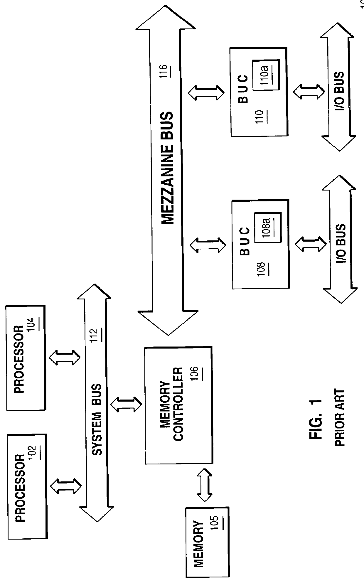
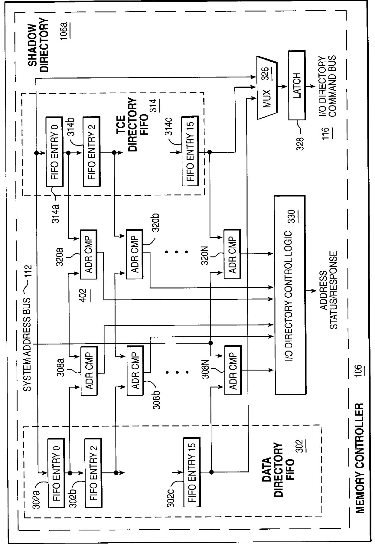
Reference now being made to FIG. 2, a schematic diagram is shown illustrating a Shadow Directory 106a that can reside in the memory controller 106 of FIG. 1 in accordance with the teachings of the present invention. The Shadow directory 106a includes a D...


PUM


Abstract

In multi-processor systems which have separated the system bus from the I/O bus, a Shadow Directory is introduced into the memory controller for reducing bottlenecks that occur from the processors snooping data cache in the I/O devices residing on the I/O bus. This Shadow Directory is advantageously employed in a system, such as the PowerPc architecture which distinguishes between the types of data that can be cached in I/O devices. The Shadow Directory uses two First In First Out (FIFO) stacks for two different types of data. These FIFO stacks are then used for addresses placed on the system bus and I/O bus in order to reduce snoop latency times.

Description

1. Field of the Present InventionThe present invention generally relates to data processing systems, and more specifically, to methods and apparatuses in the systems that reduce system latency.2. History of Related ArtThe evolution of the computer industry has been driven by the insatiable appetite of the consumer for ever increased speed and functionality. One species that the evolution has created is the multi-processor computer.Multi-processor systems, in similarity to other computer systems, have many different areas that are ripe for improvement. One such area ripe for improvement results from the current design implementations for multi-processor systems. Specifically, these multi-processor systems have a number of bottlenecks that degrade their overall performance. For instance, those; and skilled in the art are well aware of the difficulty of increasing processor performance due to the inability to keep the processors and their respective caches supplied with instructions an...

Claims


Application Information

Patent Timeline
Patent Type & Authority Patents(United States)
IPC IPC(8): G06F12/08
CPCG06F12/0835
Inventor ARIMILLI, RAVI KUMARKAISER, JOHN MICHAELMAULE, WARREN EDWARD
Owner GOOGLE LLC
Why Eureka
Try Eureka