Tire manufacturing drum having simultaneous axial and radial adjustability

a technology of axial and radial adjustment and tire manufacturing drum, which is applied in the manufacture of tires, domestic applications, other domestic articles, etc., can solve the problems of increasing the cost of tire manufacture, excessive undercutting of sidewalls relative to the body of tires, and operator inordinate danger

Inactive Publication Date: 2000-05-09
DAVIAN ENTERPRISES LLC
View PDF5 Cites 37 Cited by
  • Summary
  • Abstract
  • Description
  • Claims
  • Application Information

AI Technical Summary

Benefits of technology

The six wider segments constitute a third group and are slave-mounted to the first and second linkages which mount the six narrow segments of the first and second groups. That is, axial and radial movement of the wider segments follows the movement of the narrow segments, but the wider segments are not mounted directly to the hubs. The mounting of the wider segments includes a cam-adjusted predetermined path of movement of the wider segments as the more narrow segments move, such path permitting the narrow segments to move axially and radially out o...

Problems solved by technology

As an additional factor, the relatively great weight of the OTR tires also makes it necessary that the green tire be easily removed from the drum inasmuch as the weight of the OTR green tire does not lend itself to manual manipulation of the tire in an effort to remove it from the drum, as is possible in certain smaller sized (and lighter weight) tires.
However, in the instance of OTR and similar tires, there is an extensive undercut of the sidewalls relative to the body of the tire.
Dismantlement, even partial, of the drum increases the cost of manufacture of a tire due to the time involved in dismantlement and reassembly of the drum, and exposes an operator to inordinate danger in the handling of the relatively large and heavy segments of the drum.
This design suffers from the complicated mechanisms ...

Method used


Image

  • Tire manufacturing drum having simultaneous axial and radial adjustability
  • Tire manufacturing drum having simultaneous axial and radial adjustability
  • Tire manufacturing drum having simultaneous axial and radial adjustability

Examples


Embodiment Construction

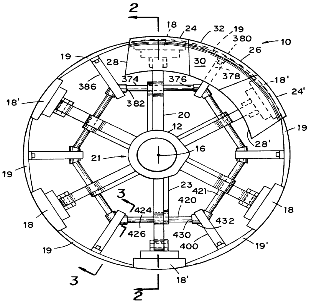
In FIG. 1, there is depicted an end view of one embodiment of a drum 20 in its expanded, maximum diameter, attitude and embodying various of the features of the present invention. Referring to FIGS. 1 and 21, the depicted drum 20 includes a central tubular housing, indicated generally by the numeral 21, a first plurality of narrow segments 18, and a second plurality of segments 19. All of the segments 19 are alike and are wider than the segments 18. As depicted in FIG. 21, the total depicted segments 1-12 make up one end portion of segments. The odd-numbered narrow segments 1,5 and 9 make up a first group 15 of narrow segments. The odd-numbered narrow segments 3,7 and 11 make up a second group 17 of narrow segments. The even-numbered segments 2,4,6,8,10 and 12 make up a third group 23 of wide segments. All of the narrow segments are substantially alike, but they are divided into two groups based upon their relative axial and radial movements. The narrow segments in group 15 are desi...


PUM

PropertyMeasurementUnit
Widthaaaaaaaaaa
Circumferenceaaaaaaaaaa

Abstract

A rotatable drum (10) for use in the manufacture of vehicle tires, the drum including a plurality of segments which collectively define an outer circumference (32) of the drum. The segments are divided into first and second end portions (15,17) which are individually mounted for axial and radial movement between expanded and retracted positions relative to the rotational axis (16) of the drum. Each end portion of segments is further divided into first and second groupings (23,25), the segments (18,18') of the first and second groupings (23,25) being disposed in alternating juxtaposition with respect to the segments of the second grouping (18') and with the segments of the first grouping being movable axially further and radially faster than the segments of the second grouping as the segments are moved between their expanded and retracted positions so that the segments of the second grouping are received in overlying relationship to the segments of the first grouping as the segments of the first and second groupings are simultaneously moved radially inward toward the rotational axis of the drum. A third grouping 23 of the segments of each end portion of segments is provided for, with these segments (19,19') being received in overlying relationship to the segments of the first and second groupings. Further, in a preferred embodiment, each segment is provided with a shell member (24,26), with the shell members collectively defining the outer cylindrical surface (32) of the drum. A method for the production of a rotatable cylindrical drum (10) and a method for the manufacture of an OTR vehicle tire are disclosed.

Description

BACKGROUND OF INVENTIONThis invention relates to apparatus for use in the manufacture of vehicle tires, especially off-the-road (OTR) tires,(including aircraft tires) and to methods for the manufacture of such tires.In the manufacture of vehicle tires it is common practice to fabricate a tire in steps or "stages". Most usually, the multiple stages employed are carried out on different pieces of apparatus and the product(s) from one stage are transferred to a different stage of operation for further work on the product and / or combination of this product with a further product.In one example, the manufacture of a vehicle tire includes the step of forming a carcass for the tire on a first piece of apparatus, forming a belt and tread package for the tire on a separate piece of apparatus, and thereafter marrying the belt and tread package to the carcass, commonly employing a further piece of apparatus, to form a "green" tire. In the manufacture of either of the carcass or the belt and tr...

Claims


Application Information

Patent Timeline
IPC IPC(8): B29D30/24B29D30/20
CPCB29D30/248
Inventor ROBERTS, CLARK A.BYERLEY, MARK S.
Owner DAVIAN ENTERPRISES LLC
Why Eureka
Try Eureka