Suturing apparatus and method

a technology of suction apparatus and suction clamp, which is applied in the field of suction apparatus and method, can solve the problems of irritating the individual applying pressure, wounds to the tissue of the human body, and puncture sites

Inactive Publication Date: 2000-05-09
APPL MEDICAL RESOURCES CORP
View PDF20 Cites 317 Cited by
  • Summary
  • Abstract
  • Description
  • Claims
  • Application Information

AI Technical Summary

Benefits of technology

In one aspect of the invention, the suturing apparatus includes an elongate support structure having an axis extending between a proximal end and a distal end. A receiver disposed at the distal end is sized and configured to fit through the small incision and to provide structural support for the tissue on the far side of the body wall. One end of a suture is carried by a needle through the tissue surrounding the incision and into the receiver in an expanded state. The receiver has characteristics for capturing the suture end so that removal of the apparatus carries the suture end through the incision to facilitate tying of novel knot construction to close the incision.
In an associated method for closing the incision, the receiver is inserted through the incision from the near side of the body wall to the far side of the body wall. The first end of a suture is moved from the near side through the surrounding tissue and embedded in the receiver on the far side of the body wall. After the receiver captures the first end of the suture, it can be withdrawn from the far side of the wall through the incision bringing the first end of the suture exteriorly of the patient into proximity with the second end of the suture. A novel knot construction can then be tied to facilitate an abutting relationship between opposing edges of the incision.
In still a further aspect of the invention, an associated method includes the step of providing the hollow distal end of the shaft with first and second guide slots. The suture is attached to the first stylet on the near side of the body tissue and a portion of the suture moved by the first stylet to the far side of the body tissue. A second stylet is moved to the far side of the body tissue where it engages the suture portion. Moving the second stylet, and the engaged suture portion, from the far side to the near side of the body tissue, permits the tying of the suture to close the wound. Transfer of the suture portion from the first stylet to the second stylet can occur between the guide slots which may be opened or closed at the distal end of the shaft.

Problems solved by technology

Wounds to tissue of the human body can occur accidentally or by way of an incision resulting from a surgical procedure.
Small wounds or incisions, such as puncture sites, offer particular challenges since the far side of the body wall is not readily accessible for suturing.
Unfortunately, this procedure requires that the individual press on the site for an extended period of time.
This requires the presence of another person in the surgical environment, but also can be very tiring to the individual applying pressure.
These weights do not benefit from the variable application of pressure which the individual can provide in the digital pressure technique previously discussed.
Plugs and adhesives have also been used but these typically leave some projection into the body cavity or conduit which tends to interfere with the natural flow of fluids.
It can be seen that these present methods and materials are cumbersome, time-consuming, and potentially problematic.
Closure of this incision in the interior blood vessel is complicated by the fact that the percutaneous incision is small and provides little opportunity for accessing the interior of blood vessel.
This can be accomplished only with considerable trauma to the patient.
The process is very difficult to perform in the limited space available and the resulting suture is often ineffective.
Unfortunately, this device sutures from the inside of the vessel and, therefore, requires that the bulk of the device initially be passed through the wound or incision to the far side of the vessel wall.
Accordingly, this device is not capable of addressing small punctures or incisions.
In this context, access to the far side of the body wall (the vessel wall in this case) is extremely limited.

Method used


Image

  • Suturing apparatus and method
  • Suturing apparatus and method
  • Suturing apparatus and method

Examples


Embodiment Construction

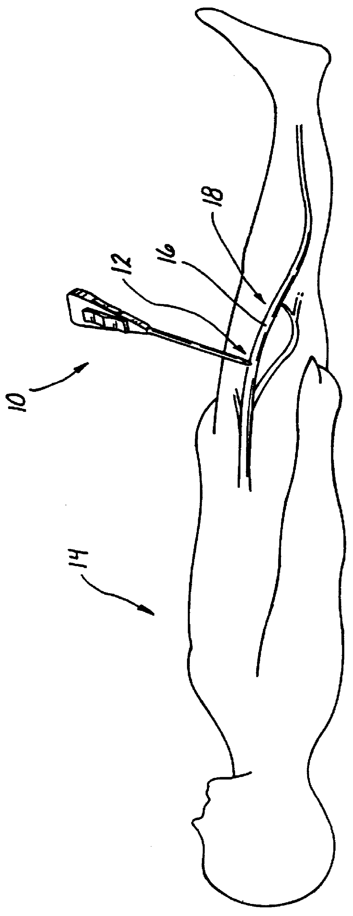
A suturing apparatus is illustrated in FIG. 1 and designated generally by the reference numeral 10. This apparatus 10 is particularly adapted for use in closing an interior wound or incision 12 of a patient 14. In FIG. 1, the incision 12 is made in a wall 16 of the femoral artery, vein, or other vessel 18 in preparation for the insertion of a catheter (not shown). Access to the interior vessel 18 is gained percutaneously through a cut 23 in the skin 25 of the patient 14.

In a manner well-known to those skilled in the art, the incision 12 is created in the wall 16 and a guidewire 21 is introduced into the vessel 18. This guidewire 21 facilitates insertion of the catheter (not shown) over the guidewire 21 and into the vessel 18. The present invention contemplates closure of the incision 12 after this primary procedure has been completed and the catheter removed.

In the illustrated example, the wall 16 of the vessel 18 is merely representative of any facial or tissue wall having a near s...


PUM


Abstract

A suturing apparatus is adapted for joining two objects which define a near side and a far side. The apparatus includes an elongate support structure having a working channel and an axis extending between a proximal end and a distal end. The structural support is adapted to be positioned over a guidewire extending between the two objects, in an operative position wherein the proximal end is disposed on the near side and the distal end as disposed on the far side. Removal of the guidewire permits use of a stylet for positioning a suture to extend within the working channel from the proximal end to the distal end. A pair of hooks are movable from a proximal position at the proximal end of the support structure through the objects and a pair of slots in the support structure, to a distal position wherein the hooks engage the suture within the working channel at the distal end of the support structure. The actuator is then operable to move the hooks and the engaged suture from the distal position to the proximal position in order to facilitate tying of the suture and joining of the two objects. Alternatively, suture loops can be carried through the objects by unidirectional hooks and into the working channel. The hooks can then be withdrawn leaving the suture loops in the working channel where they can be engaged by a snare and withdrawn proximally between the two objects. Suturing pledgets can be added to the suturing apparatus prior to operative disposition, and a backing member can be provided to support at least the pledgets when the hook passes through the object.

Description

BACKGROUND AND FIELD OF THE INVENTIONThis invention relates generally to suturing apparatus and methods and, more specifically, to such apparatus adapted for closing tissue wounds or incisions in a tissue wall.DISCUSSION OF THE PRIOR ARTWounds to tissue of the human body can occur accidentally or by way of an incision resulting from a surgical procedure. In either event, the tissue is pierced and the resulting incision or wound requires closure. The tissue will typically form a body wall having a near side and a far side with the incision or wound defined by surrounding tissue. The body wall will typically define a body cavity, such as the bladder, or a body conduit, such as a vessel. Small wounds or incisions, such as puncture sites, offer particular challenges since the far side of the body wall is not readily accessible for suturing.The closure of a puncture, incision, or access site is desirable primarily to control bleeding. In the past, this bleeding has been addressed with ma...

Claims


Application Information

Patent Timeline
Patent Type & Authority Patents(United States)
IPC IPC(8): A61B17/04A61B17/00A61B17/06
CPCA61B17/0469A61B17/0625A61B17/0483A61B17/0057A61B17/0482A61B2017/0472A61B2017/00637A61B2017/00663
Inventor HART, CHARLES C.HILAL, NABIL
Owner APPL MEDICAL RESOURCES CORP
Why Eureka
Try Eureka