
Leaning recumbent tricycle

a recumbent, tricycle technology, applied in the field of tricycles, can solve the problems of compromising the accuracy of leaning moments, all the driver's points of contact, seat, handlebars and pedals, and moving with the leaning front section

Inactive Publication Date: 2000-05-16
STITES WILLIAM J
View PDF17 Cites 41 Cited by
  • Summary
  • Abstract
  • Description
  • Claims
  • Application Information

AI Technical Summary

Problems solved by technology

A primary disadvantage of this embodiment is that all of the driver's points of contact, that is, the seat, the handlebars and the pedals, are moving with the leaning front section.
In this way, the driver cannot exert a force directly between and including the front and rear sections, whereby accuracy of leaning moments is greatly compromised.
Indeed, the driver must shift his / her weight with little hope of correcting an overshift or undershift during a critical turn.
Additionally, this embodiment also exemplifies the disadvantage noted above where all the driver's points of contact are moving with the leaning front section, resulting in less control of leaning than can be accomplished by the tricycle of the invention.
Thus, in no prior art cited is the driver afforded direct control of the amount of lean by way of the hands.
A disadvantage of this arrangement is the large amount of lateral displacement of the seat upon leaning.
Since the driver upon the seat represents a majority of the vehicular mass, this lateral displacement results in a considerable shift of the center of gravity of the vehicle from the midline.
Problems such as traffic congestion, pollution, pedestrian intimidation, social isolation, etc., have developed gradually in the cities of the world and are largely a result of the over-utilization of cars and trucks.

Method used


Image

  • Leaning recumbent tricycle
  • Leaning recumbent tricycle
  • Leaning recumbent tricycle

Examples


Embodiment Construction

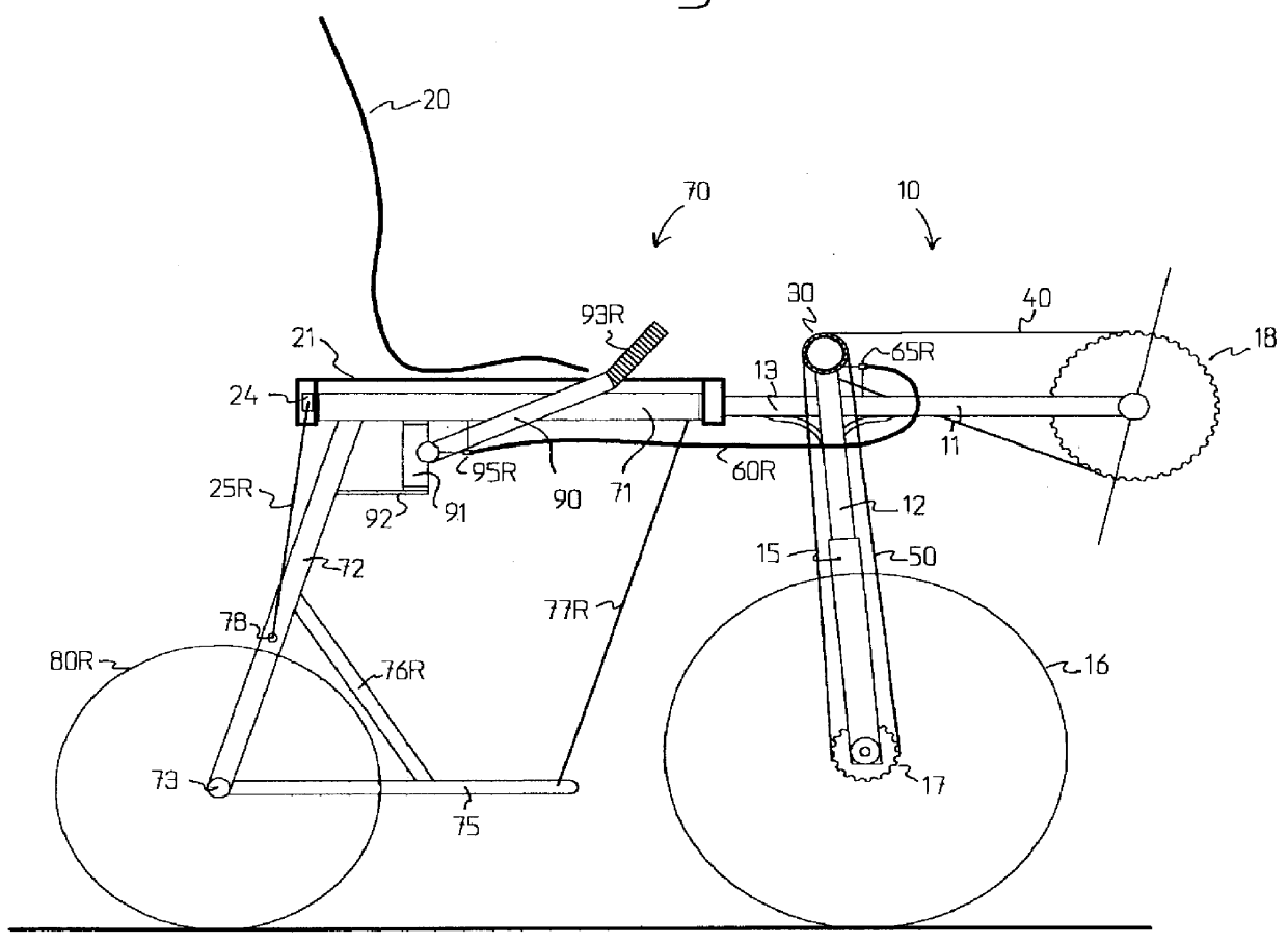
FIG. 1 shows a side view of the tricycle of the invention. Parts of the front sub-frame (10) that are illustrated include a pedal crank (18) that is supported by a boom (11), that is affixed to the front of the head tube (12). The top chain (40) links the pedal crank (18) to the u-joint hub (30). The front top tube (13) is affixed to the rear of the head tube (12). The steer tube (14), which is not visible in this view, passes through the head tube (12) and is affixed to the top of the front fork (15). The front wheel (16) is held at its axle by the front fork. The down chain (50) links the u-joint hub (30) to the front wheel hub (17). The seat (20) is mounted over the seat bar (21), which is affixed to the front top tube (13). The right lean restraint cable (25R) is supported at its top by the mounting bar for lean restraint cables (24), and at its bottom by the mount for bottom of lean restraint cables (78). Since the two rear wheels (80L, 80R) are side by side, only the right rea...


PUM


Abstract

A human-powered recumbent tricycle with an articulated frame that permits leaning of the single-wheeled front sub-frame (10) during turns. While the seat (20) and pedal crank (18) move the driver's body with the leaning front sub-frame (10), the two-wheeled rear sub-frame (71) carries the handlebar (90) for optimum driver control of vehicular orientation. Steering of the front wheel (16) is accomplished by two cables (60L, 60R) within housings (61L, 61R) that provide immunity from distortions caused by articulation (100) rotations during leaning. Front wheel (16) drive utilizes a universal joint hub (30) for continuous power drive and no chain (40, 50) twist throughout the full turning radius. High seat (20) height and narrow wheelspan of the two rear wheels (80L, 80R) provide for improved visibility and traffic penetration on congested urban streets. A low cargo rack (75) is provided such that carrying cargo lowers the overall center of gravity and increases vehicular stability. Since the front wheel (16) drive system is self-contained within the front sub-frame (10), the rear sub-frame (70) is interchangeable with other rear sub-frame (70) configurations; whereby this modular system can create vehicles for personal transportation, delivery, pedicabs, flat-bed trucks, and other custom needs; all with the same front drive sub-frame (10).

Description

1. Field of InventionThe tricycle of the invention is in the field of human-powered vehicles.2. Discussion of Prior ArtU.S. Pat. No. 5,240,267 to Owsen shows a human-powered leaning tricycle. This appears to be the closest prior art to the invention, as front wheel drive is also specified. However, the driver position is not recumbent, but shows instead a somewhat standard upright bicycle riding position. A primary disadvantage of this embodiment is that all of the driver's points of contact, that is, the seat, the handlebars and the pedals, are moving with the leaning front section. In this way, the driver cannot exert a force directly between and including the front and rear sections, whereby accuracy of leaning moments is greatly compromised. Indeed, the driver must shift his / her weight with little hope of correcting an overshift or undershift during a critical turn.U.S. Pat. No. 3,583,727 to Wallis shows several leaning tricycles. The preferred embodiment is not human-powered. H...

Claims


Application Information

Patent Timeline
IPC IPC(8): B62K5/00B62K3/00B62K5/04B62K5/02
CPCB62K3/005B62K5/10B62K5/02
Inventor STITES, WILLIAM J.
Owner STITES WILLIAM J
Features
  • Generate Ideas
  • Intellectual Property
  • Life Sciences
  • Materials
  • Tech Scout
  • Unparalleled Data Quality
  • Higher Quality Content
  • 60% Fewer Hallucinations
Learn More