Information recording medium which indicates information according to the wobbling of a track and information recording and reproducing apparatus

a technology of information recording and information recording, which is applied in the field of information recording and reproducing apparatus, can solve the problems of increasing leakage of information from adjacent tracks, inability to use a track width smaller than the diameter of the laser beam in reproduction, and difficulty in reproducing information correctly

Inactive Publication Date: 2000-05-30
HITACHI CONSUMER ELECTRONICS CORP
View PDF7 Cites 142 Cited by
  • Summary
  • Abstract
  • Description
  • Claims
  • Application Information

AI Technical Summary

Problems solved by technology

However, the above technique in JP-A-49-103515 is unable to use a track width smaller than the diameter of the beam spot of the laser beam in reproduction.
The reason for this

Method used


Image

  • Information recording medium which indicates information according to the wobbling of a track and information recording and reproducing apparatus
  • Information recording medium which indicates information according to the wobbling of a track and information recording and reproducing apparatus
  • Information recording medium which indicates information according to the wobbling of a track and information recording and reproducing apparatus

Examples


first embodiment

the present invention will be described.

To begin with, an optical disk according to the first embodiment of the present invention will be described.

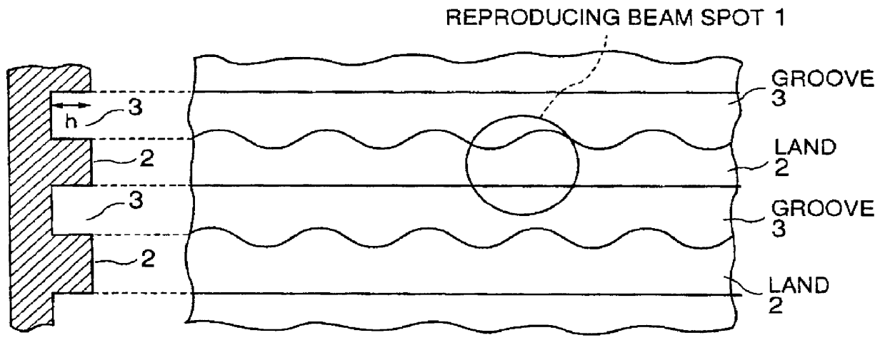
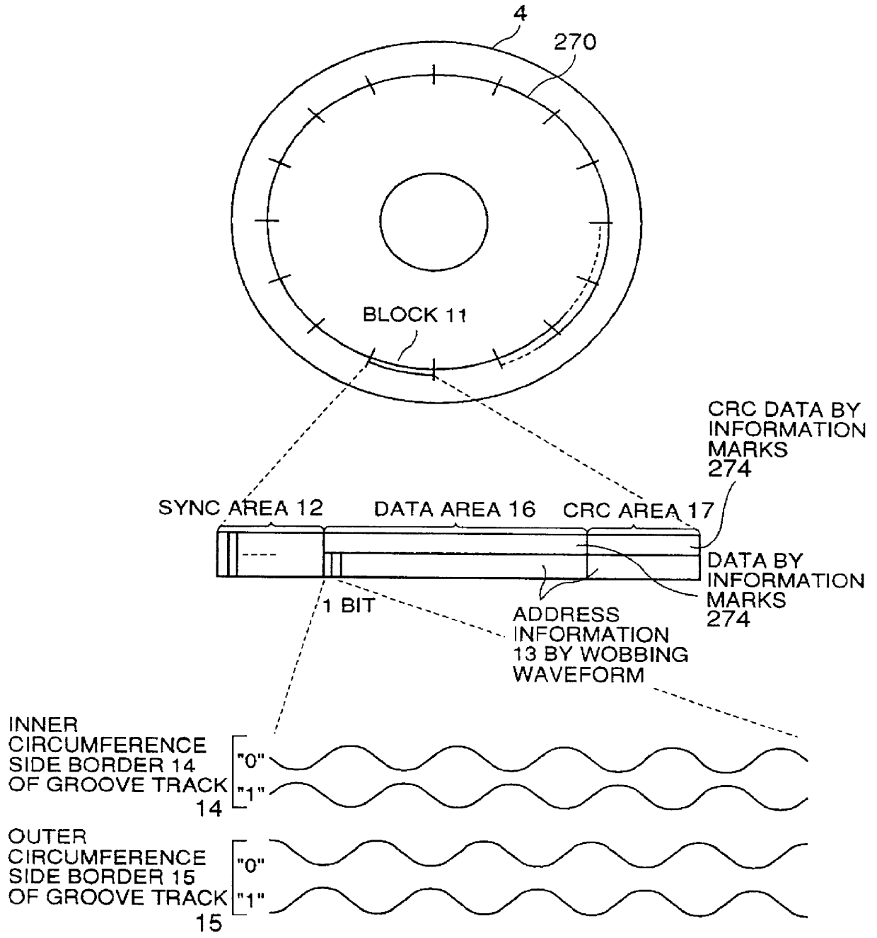
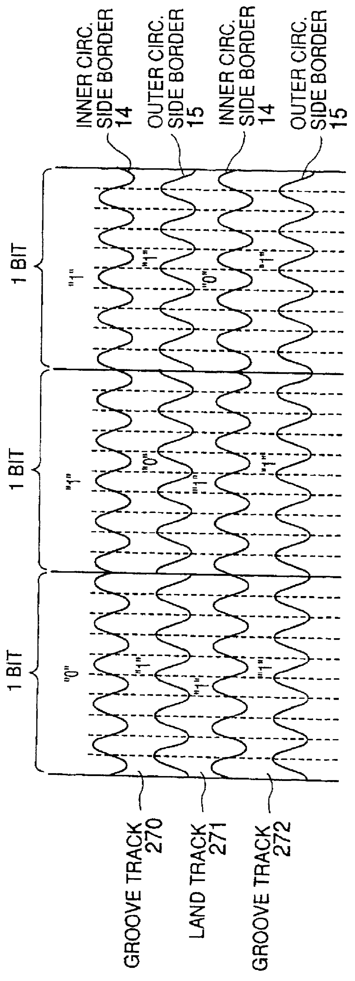
As shown in FIGS. 2 and 27, an optical disk 4 according to the first embodiment is formed as an optical disk of the land / groove track structure which uses grooves 270, 272, etc. and lands 269, 271, 273, etc. as the tracks formed mutually spaced a fixed distance apart in a spiral form with respect to the center of the disk. As shown in FIG. 2, one circuit of the track 270, for example, is divided into an integral number of blocks 11, and each block 11 is divided into a synchronous (sync) area 12, a data area 16, and a CRC area 17. The blocks 11 may be provided by a generally well-known method. For example, the CAV (Constant Angular Velocity) method may be used in which the number of blocks 11 per circuit of the track is the same from the innermost track to the outermost track of the optical disk 4, or the M-CAV (Modified CAV) method may b...

sixth embodiment

Finally, description will be made of the present invention.

In this embodiment, the method of detecting a track shift signal without offset will be discussed.

When the reproducing beam spot goes across a track, output of the differential detector 38, shown in FIG. 20, which has a similar circuit structure as in FIG. 5A is represented by the signal 521 in FIG. 21, having a wobbling frequency component (the dotted line) superimposed on the track shift signal (the solid line). At this time, as the center of the beam on the two-piece detector 33 of FIG. 5A deviates from the split center of the two-piece detector 33, offset occurs in the signal 512 of FIG. 21, and the position of the zero point of the track shift signal shifts from the center of the track, such as 270. Only the wobbling frequency component is extracted from the signal 521 by the band filter 39, then signals 522 and 523 are obtained as outputs of the synchronous detectors 42, 43. Specifically, the wobbling frequency compone...


PUM


Abstract

An optical disk comprising a substrate 4, and a plurality of tracks 269 to 273 formed on the substrate 4, wherein the plurality of tracks 269 to 273 include groove tracks 270, 272 consisting of a plurality of grooves mutually space apart by a fixed space, and land tracks 269, 271, 273 consisting of areas between the groove tracks, wherein the borders 14, 15 between the groove tracks and the land tracks represent information using the waveforms from their wobbling patterns, wherein the period of the wobbling waveforms of the borders 14, 15 are constant on each border, but the wobbling waveforms of the opposite portions of the borders across the track are shifted in phase by a predetermined phase difference.

Description

1. Field of the InventionThe present invention relates to an information recording medium for optically recording or reproducing information, and an information recording and reproducing apparatus for recording or reproducing information on the information recording medium.2. Prior ArtOptical disks are known, such as compact disks and magnetooptical disks, which optically record information by changes in the reflectance factor or changes in the polarization direction of reflected light, for example. A track 261 is formed in a spiral form on the surface of an optical disk as shown in FIG. 26. Along this track on the optical disk, information marks caused by the changes in the reflectance factor or the changes in the polarization direction of the reflected light are formed to record information on a surface of an optical disk 260.A circuit of the track 261 is divided into an integral number of blocks 262. Each block 262 is divided according to a predetermined disk format into a plural...

Claims


Application Information

Patent Timeline
IPC IPC(8): G11B27/30G11B27/24G11B27/19G11B7/007G11B7/26G11B7/24082
CPCG11B7/0053G11B7/007G11B7/00718G11B7/00745G11B7/261G11B27/19G11B27/24G11B27/3027G11B7/24082G11B2220/20
Inventor MAEDA, TAKESHIMIYAMOTO, HARUKAZU
Owner HITACHI CONSUMER ELECTRONICS CORP
Why Eureka
Try Eureka