Touch screen

a touch screen and touch technology, applied in the field of touch screens, can solve the problems of unintended functions of devices or systems connected to the touch screen or input device, difficult operation of known touch screens and input devices comprising touch screens, and even more pronounced problems

Inactive Publication Date: 2000-06-06
TELEFON AB LM ERICSSON (PUBL)
View PDF22 Cites 182 Cited by
  • Summary
  • Abstract
  • Description
  • Claims
  • Application Information

AI Technical Summary

Problems solved by technology

Whilst the known touch screens and input devices comprising touch screens described above function quite adequately in controlled environments, they do have a number of drawbacks.
The known touch screens and input devices comprising touch screens are difficult to operate.
In many cases such an unintended activation gives as a result that a device or system connected to the touch screen or input device performs an unintended function.
This problem becomes even more pronounced when the prior art touch screen or input device is used out of sight of the user and / or when the user is on the move (for example walking).
Such a relative large surface area of a touch screen or an input device is incompatible with the use on or in physically small devices.
This problem is more pronounced when the touch screen or input device is used out of sight of the user and / or when the user is on the move (for example walking).
This problem is especially pronounced in the cases when a number of predetermined regions of the active surface area of a touch screen is needed on a physically small device.

Method used


Image

  • Touch screen
  • Touch screen
  • Touch screen

Examples


first embodiment

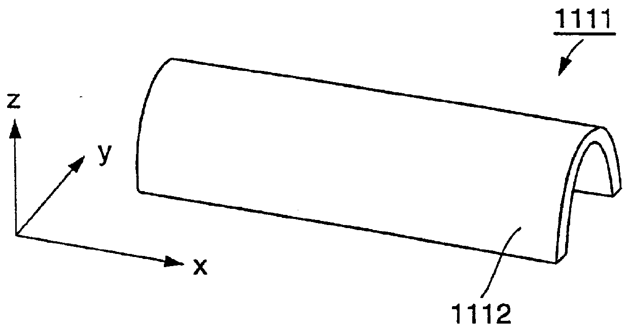
FIG. 2 schematically illustrates a perspective view of a touch screen 1111 according to the present invention. FIG. 3a to FIG. 3d schematically illustrate a cross-sectional view of the touch screen 1111 in a plane which is perpendicular to the x-direction as defined in FIG. 2. FIG. 3e schematically illustrates a cross-sectional view of the touch screen 1111 when it has been assembled with an apparatus 1141. The touch screen 1111 is formed to have a substantially U-shaped cross-section as is shown in FIG. 3a to FIG. 3d. The touch screen 1111 has an active surface area 1112 at an "outer" surface of the U-shaped structure. The U-shape may be achieved by bending a conventional touch screen. FIG. 3a illustrates the touch screen 1111 when it is untouched. FIG. 3b and FIG. 3d illustrates the touch screen 1111 when it is experiencing the presence of an object on a first and a second "leg" of the U-shaped structure, respectively. FIG. 3c illustrates the touch screen 1111 when it is experienc...

second embodiment

FIG. 4 schematically illustrates a perspective view of a touch screen 1211 according to the present invention. FIG. 5a to FIG. 5d schematically illustrate a cross-sectional view of the touch screen 1211 in a plane which is perpendicular to the x-direction as defined in FIG. 4. The touch screen 1211 is formed to have a substantially U-shaped cross-section as is shown in FIG. 5a to FIG. 5d. The touch screen 1211 has an active surface area 1212 at an "inner" surface of the U-shaped structure. The U-shape may be achieved by bending a conventional touch screen. FIG. 5a illustrates the touch screen 1211 when it is untouched. FIG. 5b and FIG. 5d illustrates the touch screen 1211 when it is experiencing the presence of an object on a first and a second "leg" of the U-shaped structure, respectively. FIG. 5c illustrates the touch screen when it is experiencing the presence of the object on the "curved" part of the U-shaped structure. In the example of FIG. 5b to FIG. 5d the above mentioned ob...

fourth embodiment

In cases of the touch screens of the third or fourth embodiment the presence of an object may be detected by sensing a pressure of the object against the touch screen. The object may refer to the tip of a finger of a user.

The active surface areas 1312, 1412 of the touch screens 1311, 1411 discussed above in the third and fourth embodiments extend in three physical dimensions. The substantially round or elliptical shape of the touch screens 1311, 1411 in a top view perspective which protrudes towards or away from a user is given such dimensions that a user may slide his finger over the active surface areas 1312, 1412 and thereby, due to the tactile feedback from the round or elliptical shape, the user can be informed about the position of the finger at the active surface area.

In alternative embodiments, the substantially round or elliptical shape of the active surface areas 1312, 1412 of the touch screens 1311, 1411 of the third and fourth embodiments is given such dimensions that a ...


PUM


Abstract

A touch screen 1111 having an active surface area 1112 which extends in three physical dimensions (x-, y- and z-dimensions) is provided. In the figure the active surface area has an U-shaped form. When a user slides his finger over the active surface area the tactile feedback gives him information about the position of the finger. The touch screen is activated when the active surface area senses a certain pressure from the finger. The use of the touch screen is facilitated especially when the user is on the move or when the touch screen is out of sight. Such use is common when operating hand-held terminals.

Description

The invention refers to touch screens having active surface areas for sensing the presence of an object at and / or at a small distance from the active surface areas. The invention also refers to the use of such touch screens. Furthermore the invention refers to a method of manufacturing such touch screensDESCRIPTION OF RELATED ARTInput devices for use in computer environments are known in the prior art. These are used to input data to a computer based system. Such data may be used to navigate a cursor on a display, to control the functions of a certain device or to simply input information to a system.An input device may comprise a touch screen. A "touch" on a touch screen means that the touch screen senses the presence of an object such as a tip of a finger of a user or another object, for example a stylus, at and / or at a small distance from an active surface area of the touch screen. An output signal which, in general, is either an electrical or an optical signal is generated from ...

Claims


Application Information

Patent Timeline
Patent Type & Authority Patents(United States)
IPC IPC(8): G06F3/033G06F3/02H01H13/702H01H13/70G06F3/0354G06F3/0362G06F3/041H01H13/807
CPCG06F3/0213G06F3/0362G06F3/0414H01H13/702H01H13/807G06F3/03547H01H2231/022G06F2203/0339G06F2203/04809H01H2215/00H01H2217/026H01H2217/028H01H2219/012H01H2221/014H01H2221/016H01H2223/022H01H2225/022
Inventor VAN KETWICH, JOHAN RICHARD
Owner TELEFON AB LM ERICSSON (PUBL)
Why Eureka
Try Eureka