Method and system for imaging target detection

Inactive Publication Date: 2000-06-06
RAYTHEON CO
View PDF8 Cites 126 Cited by
  • Summary
  • Abstract
  • Description
  • Claims
  • Application Information

AI Technical Summary

Benefits of technology

It is a further object of this invention to provide such a method and system for imaging target detection which distinguishes and avoids targeting countermeasures such as flares.
It is a further

Problems solved by technology

In addition, since these vehicles are expendable the costs of the processor must be kept as low as possible.
This processing must be accurate at each phase because once the missile or munition is launched, no further communication with it is possible.
One problem with an infrared seeking system is that it can be difficult to discriminate between the target and background clutter.
Clutter includes weather conditions such as fog, and the existence of countermeasures such as flares and jamming devices, all of which tend to obscure the desired target within the surrounding background.
Given that any one location can expe

Method used


Image

  • Method and system for imaging target detection
  • Method and system for imaging target detection
  • Method and system for imaging target detection

Examples


Embodiment Construction

Other objects, features and advantages will occur to those skilled in the art from the following description of a preferred embodiment and the accompanying drawings, in which:

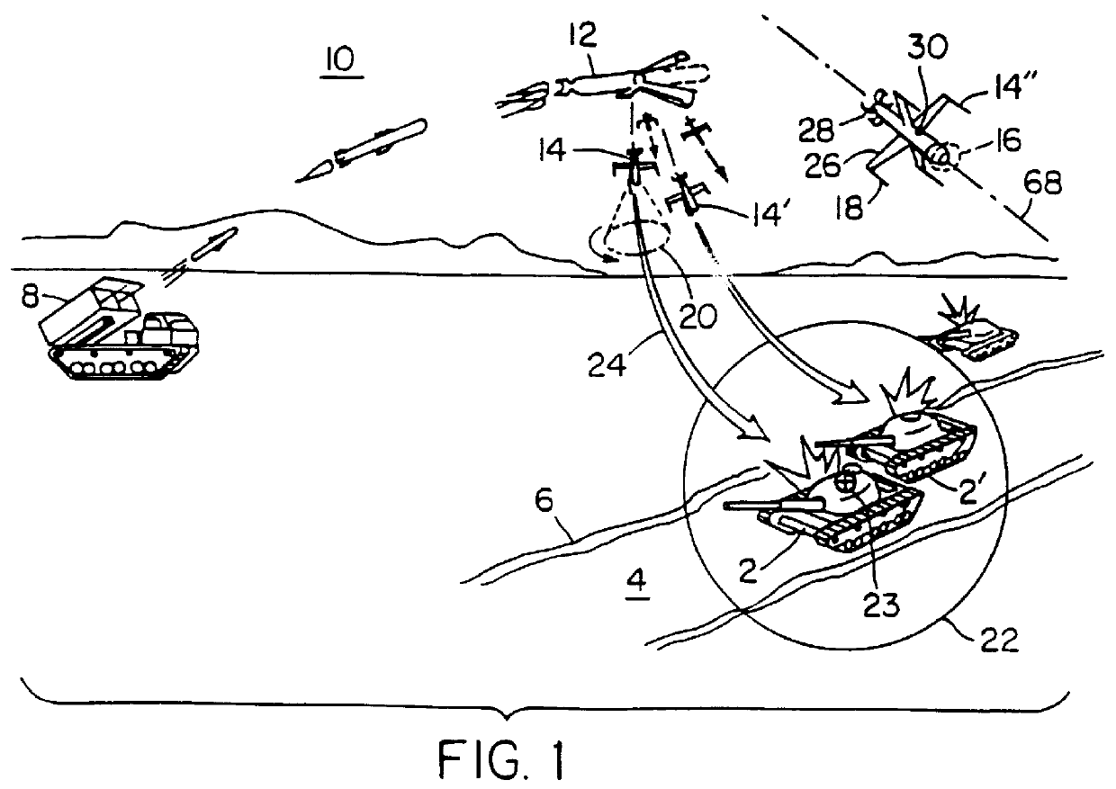
FIG. 1 is a perspective view showing the operation of a self-targeting missile on a target such as a tank;

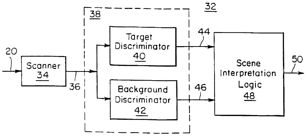
FIG. 2 is a block diagram of an imaging target detection system according to this invention;

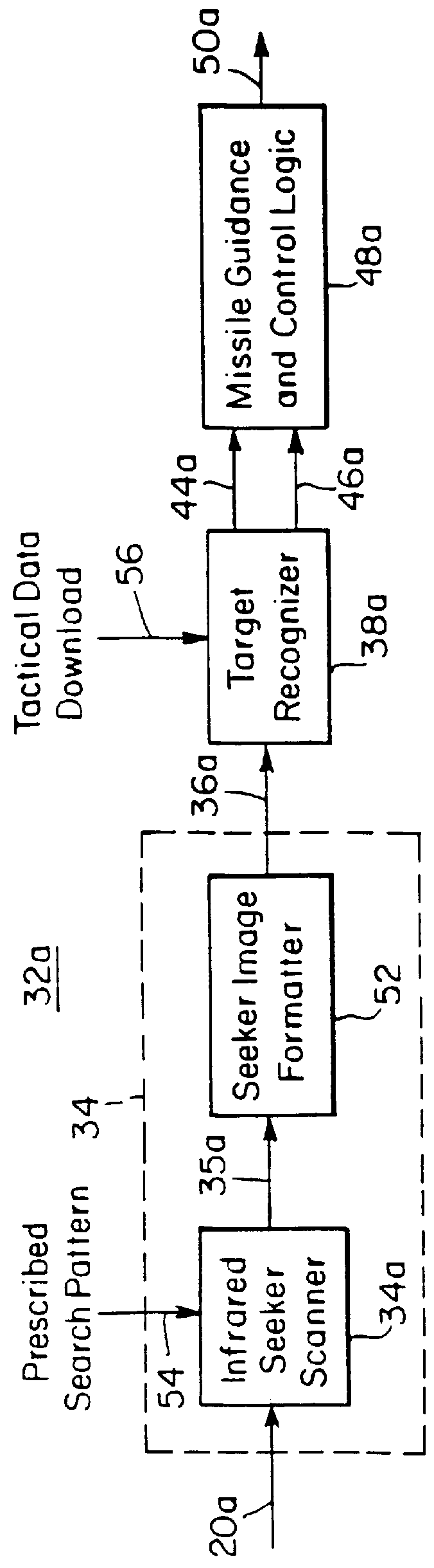
FIG. 3 is a block diagram of an embodiment of the imaging target detection system of FIG. 2;

FIG. 4 is a block diagram of the imaging target detection system of FIG. 2 employing a microprocessor;

FIG. 5 is a cross-sectional representation of an infrared seeker / scanner used in the imaging target detection system of FIG. 2;

FIG. 6 is a perspective view of a conical scan pattern of the infrared seeker / scanner of FIG. 5;

FIG. 7A is a perspective view showing a series of areal image snapshots taken during the conical scan of FIG. 6;

FIG. 7B is a flow chart of logic used to program the microprocessor in the scanner of the imagi...


PUM


Abstract

A system and method for imaging target detection includes scanning a target area to produce an image of the target area and discriminating a target by identifying image pixels of similar intensity levels, grouping contiguous pixels with similar intensity levels into regions, calculating a set of features for each region and qualifying regions as possible targets in response to the features; discriminating the background by identifying image pixels of similar intensity levels, grouping contiguous pixels of similar intensity levels into regions, calculating a set of features for each background region and qualifying background regions as terrain characteristics in response to the features and analyzing the qualified terrain characteristics and qualified target candidates to determine and prioritize targets.

Description

This invention relates to a method and system for autonomous target detection and prioritization using two-color infra-red imagery.BACKGROUND OF INVENTIONInfrared seeker systems are used in autonomous missile targeting systems for automatically selecting target objects in a cluttered background. Some munitions are free-falling aerodynamically steered vehicles having a small warhead which must be placed precisely on a target.These missiles or munitions are small devices typically having a 5" diameter housing and approximately 100 cubic inch volume. Given their size, they must be able to process target data using a minimum amount of hardware so that it will fit inside the physical housing. However, the processor also must be fast enough to process the target information in only a few seconds as the missile or munition moves toward its target. In addition, since these vehicles are expendable the costs of the processor must be kept as low as possible.There are three phases of the target...

Claims


Application Information

Patent Timeline
IPC IPC(8): F41G7/22F41G7/20G01S3/786G01S3/781G01S3/78G06K9/32G01S3/782
CPCF41G7/2226F41G7/2253G06K9/3241G01S3/781G01S3/7864F41G7/2293G06V10/255
Inventor DEAETT, MICHAEL A.DEGRAAF, ERIK J.JOHNSON, STEPHEN G.NORCROSS, MELINDA L.PAWLAK, ANTHONY J.
Owner RAYTHEON CO
Why Eureka
Try Eureka