Progressive lens elements and methods for designing and using same

a technology of progressive lenses and elements, applied in the direction of optics, instruments, optical parts, etc., can solve the problem that the overall design of conventional progressive lenses does not achieve the same balance of useful optical fields of vision, and achieve the effect of optimal performan

Inactive Publication Date: 2000-06-13
CARL ZEISS VISION AUSTRALIA HO
View PDF1 Cites 53 Cited by
  • Summary
  • Abstract
  • Description
  • Claims
  • Application Information

AI Technical Summary

Benefits of technology

an intermediate zone extending across the lens element having a surface power varying from that of the upper viewing zone to that of the lower viewing zone and including a corridor of relatively low surface astigmatism;
The lens may be rotated to achieve optimum performance for specific fitting characteristics of individual wearers. A progressive lens constructed according to the present invention may have a corridor and an optical field of vision which are substantially correct for the majority of wearers. For a wearer who requires significantly different fitting, it is possible to rotate the lens to optimise near zone inset for the individual without significantly changing the fitting cross inset.

Problems solved by technology

3) the overall design of conventional progressive lenses do not achieve the same balance of useful optical fields of vision for different categories of patients, e.g. myopes, emmetropes and hyperopes.

Method used


Image

  • Progressive lens elements and methods for designing and using same
  • Progressive lens elements and methods for designing and using same
  • Progressive lens elements and methods for designing and using same

Examples


Embodiment Construction

The following description illustrates the operation of the method of the present invention by a specific numerical example.

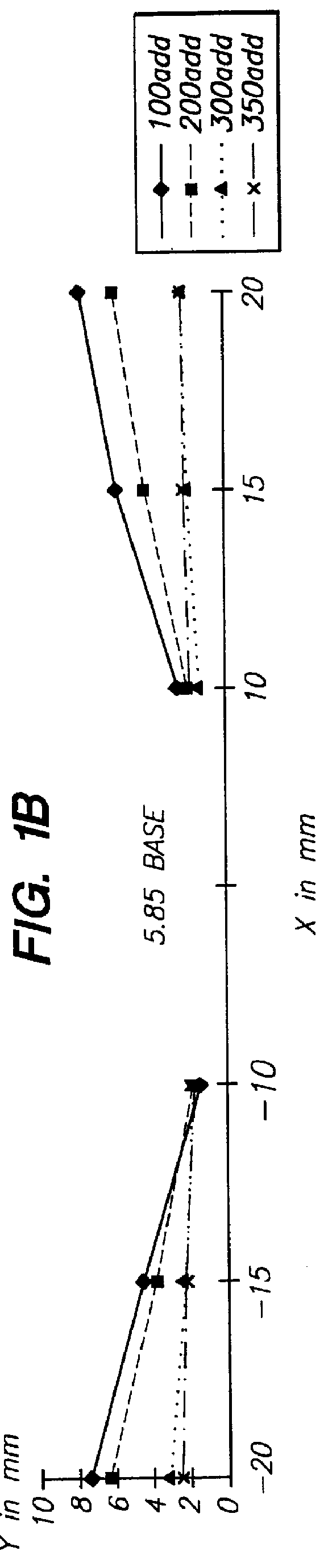
A lens element having a 5.85 D base curve and 1.00 D addition power as illustrated in FIGS. 8a, 8b and 9b, according to the present invention may be constructed as follows.

The required characteristics of the lens element are as follows:

Utilising equation (5) and incorporating an appropriate y value, y=2, and completing a ray trace as illustrated in FIG. 7 to compensate for the lens form, the inset X.sub.f is calculated at 2.34 mm.

Utilising equation (5) and incorporating an appropriate y value y=-17, then completing a ray trace as illustrated in FIG. 7 to compensate for the lens form, the horizontal inset h (at fitting cross) is calculated at 0.75 mm. Other lens elements according to the present invention were designed in a similar manner.

Finally, it is to be understood that various other modifications and / or alterations may be made without departing from the spi...


PUM


Abstract

A series of progressive ophthalmic lens elements, each lens element including a lens surface having an upper viewing zone having a surface power to achieve a refracting power corresponding to distance vision; a lower viewing zone having a greater surface power than the upper viewing zone to achieve a refracting power corresponding to near vision; a corridor of relatively low surface astigmatism connecting the upper and lower zones, said corridor having a surface power varying from that of the upper viewing zone to that of the lower viewing zone; the progressive ophthalmic lens series including a first set of lens elements having a base curve(s) suitable for use in providing a range of distance prescriptions for a first category of patient; and a second set of lens elements having a base curve(s) suitable for use in providing a range of distance prescriptions for a second category of patient; each lens element within a set differing in prescribed addition power and including a progressive design, in at least one of the upper and lower viewing zones, depending upon the addition power of the lens element; the lens elements in the first set differing substantively in progressive design from the corresponding lens elements in the second set due to the differences in base curve(s).

Description

The present invention relates to a progressive ophthalmic lens and in particular to a series of progressive ophthalmic lenses whose designs are determined by the required wearer prescription, and to a process for producing such lenses.BACKGROUND OF INVENTION AND OBJECTSNumerous progressive lenses are known in the prior art. Progressive lenses have heretofore been designed on the basis that they have distance, near and intermediate viewing zones. The intermediate zone joins the near and distance zones in a cosmetically acceptable way, in the sense that no discontinuities in the lens should be visible to people observing the lens of the wearer. The design of the intermediate zone is based on a line called the "eye path" along which the optical power of the lens increases more or less uniformly. It is normal to select an eye path to accommodate an assumed convergence of the eyes along the path beginning at a fitting cross in the distance zone and slanting nasally to the near zone.Appli...

Claims


Application Information

Patent Timeline
Patent Type & Authority Patents(United States)
IPC IPC(8): G02C7/02
CPCG02C7/027G02C7/061G02C7/066G02C7/063G02C2202/08
Inventor MORRIS, MICHAEL ALANBARKAN, ERIC FRANKLINEDWARDS, SIMON JOHNKRIS, DIMITRIOS JACKLEE, ANTHONY ALANMATTISON-SHUPNICK, MARKPERROTT, COLIN MAURICEROBERTS, KAREN LEESKLAR, DAVID HOWARD
Owner CARL ZEISS VISION AUSTRALIA HO
Why Eureka
Try Eureka