Antenna controller

an antenna controller and controller technology, applied in the field of antenna controllers, can solve the problems of increasing tracking errors, common tracking errors, and inability to reduce tracking errors

Inactive Publication Date: 2000-06-13
MITSUBISHI ELECTRIC CORP
View PDF5 Cites 12 Cited by
  • Summary
  • Abstract
  • Description
  • Claims
  • Application Information

AI Technical Summary

Problems solved by technology

In the antenna controllers described above, tracking errors are common due to sensitivity errors of the rate sensor, installation angle errors of the rate sensor, differences in the artificial reference output obtained by the lowpass filter or a drift of the reference output, rolling caused when turning the movable body, and the like.
Consequently, when using an open loop control method for controlling the antenna with information on the turning angular velocity, tracking error actually increases over time until a satellite can no longer be tracked.
Under these conditions tracking error cannot be lessened.
According to this method, if stability and band of a closed loop are restricted with respect to performance of a receiver or an antenna, an increase rate of the tracking errors caused by the drift of the reference output is sometimes greater than a decrease rate of the tracking error obtained by the closed loop control method.
For thi...

Method used


Image

  • Antenna controller
  • Antenna controller
  • Antenna controller

Examples


first embodiment

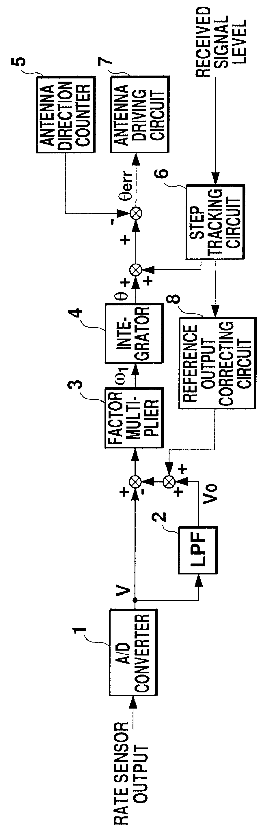
FIG. 1 is a block diagram showing an antenna controller according to a first embodiment of the present invention. In FIG. 1, the numeral 1 denotes an A / D converter for digitally converting an analog output voltage of a rate sensor, the numeral 2 denotes a lowpass filter for artificially calculating an output V.sub.0 of the rate sensor during stopping, the numeral 3 denotes a factor multiplier for converting a voltage to an angular velocity, the numeral 4 denotes an integrator for calculating a turning angle .theta. from a detected angular velocity .omega..sub.1 converted by the factor multiplier 3, the numeral 5 denotes an antenna direction counter for detecting an angle at which an antenna is driven, the numeral 6 denotes a step tracking circuit for detecting a direction in which an electric wave sent from a satellite is intensified, the numeral 7 denotes an antenna driving circuit for driving the antenna to decrease antenna direction error, and the numeral 8 denotes a reference ou...

second embodiment

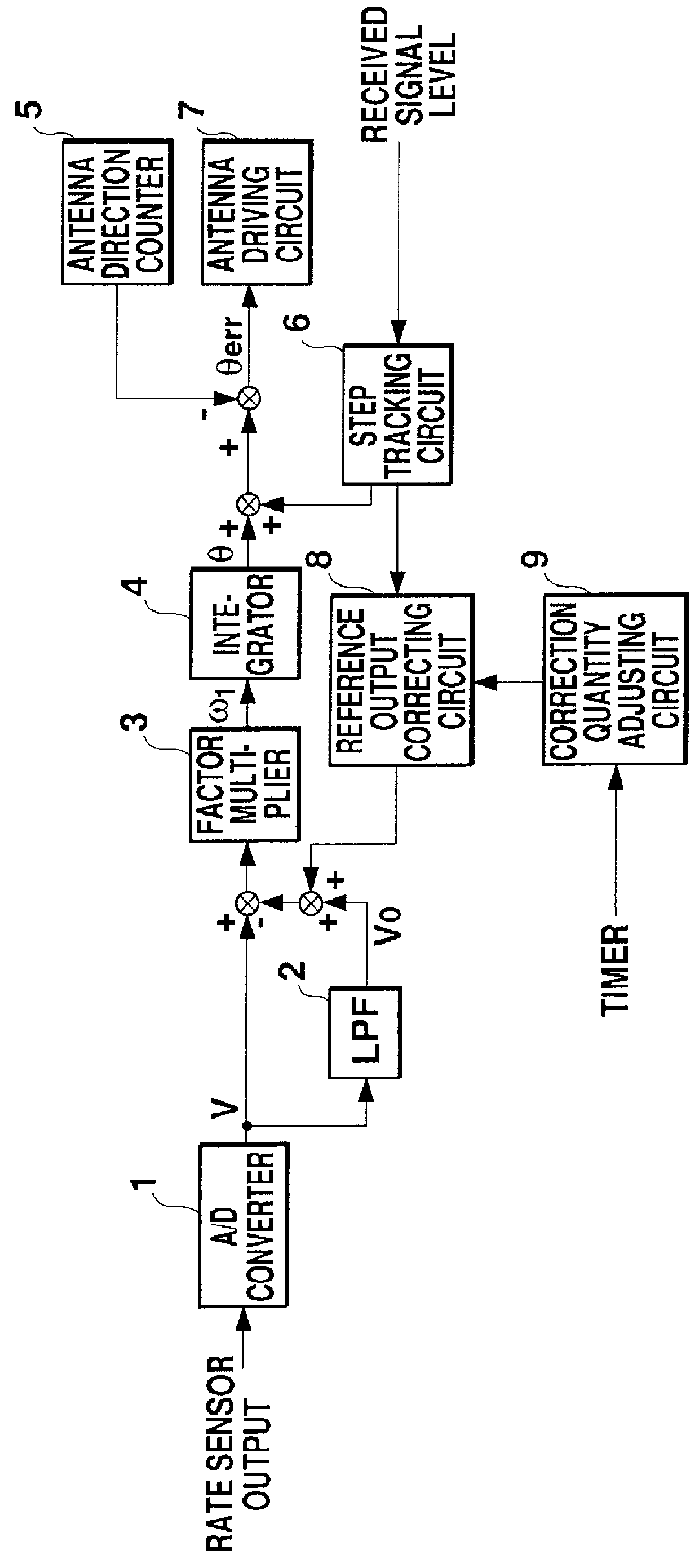
FIG. 3 is a block diagram showing an antenna controller according to a second embodiment of the present invention. In FIG. 3, parts corresponding to those in FIG. 1 are given the same number and their explanation will not be repeated. The numeral 9 denotes a correction quantity adjusting circuit for counting, by means of a timer or the like, a time taken after a rate sensor is turned on. This circuit causes a correction quantity to change after a predetermined time has passed.

Characteristics of the rate sensor to be used are first measured to acquire a relationship between the passage of time and a drift quantity of an output in a stationary state. In this case, a fluctuation rate of the drift quantity of the rate sensor is set to a value of .+-.0.00225 deg / s / s after 30 minutes have passed since the rate sensor was turned on. Accordingly, the correction quantity adjusting circuit 9 reduces the correction quantity to 2 mV. When the correction quantity is 2 mV, .+-.0.090 deg / s(=G.time...

third embodiment

FIG. 4 is a block diagram showing an antenna controller according to a third embodiment of the present invention. In FIG. 4, parts corresponding to those in FIG. 1 are given the same number and explanation will not be repeated. The numeral 9a denotes a correction quantity adjusting circuit for changing a correction quantity if an output of a rate sensor is equal to or less then a certain value or less for a certain time.

Characteristics of the rate sensor to be used are first measured and a relationship between the passage of time and a drift quantity of an output in a stationary state is acquired in the same manner as in the second embodiment. In this case, a fluctuation rate of the drift quantity of the rate sensor is set to .+-.0.00225 deg / s / s after 30 minutes have passed since the rate sensor was turned on. Accordingly, when the fluctuation rate of the drift quantity of the rate sensor is set equal to or less than .+-.0.00225 deg / s / s, the correction quantity adjusting circuit 9a ...


PUM


Abstract

An antenna controller mounted on a movable body is provided for controlling antenna driving for satellite tracking. The antenna controller comprises a step tracking circuit for performing step tracking operation on a turning face of the movable body while receiving electromagnetic waves from a satellite, and for calculating an antenna pointing direction in which an intensity of the electric wave is strongest. An antenna driving circuit drives the antenna in the antenna pointing direction, while a reference output correcting circuit adds a correction quantity to a reference output of a rate sensor based on a result of the step tracking operation.

Description

1. Field of the InventionThe present invention relates to an antenna controller mounted on a movable body for controlling an antenna drive for driving a satellite tracking antenna.2. Description of the Related ArtFIGS. 10 and 11 are block diagrams showing two examples of current structures in which a rate sensor is used for an antenna controller mounted on a movable body for satellite tracking. The rate sensors are attached to the movable body and are used to detect a turning angular velocity of the movable body. FIG. 12 is a characteristic chart showing characteristics of a rate sensor. By using the rate sensor, an output V is obtained for a turning angular velocity .omega.. A detected angular velocity .omega..sub.1 can be expressed by the following equation (1):.omega..sub.1 =G.times.(V-V.sub.0) (1)wherein .omega..sub.1 represents a detected angular velocity, G represents a factor, V represents an output of the rate sensor, and V.sub.0 represents an output in a stationary state (0...

Claims


Application Information

Patent Timeline
IPC IPC(8): H01Q3/04H01Q3/02H01Q3/10H01Q1/32H01Q3/08G01S7/03G01C19/00
CPCH01Q1/3275H01Q3/10H01Q3/04
Inventor FUKUSHIMA, TOMOAKI
Owner MITSUBISHI ELECTRIC CORP
Why Eureka
Try Eureka