Vehicle blind spot mirror

a technology for blind spot mirrors and vehicles, applied in the field of rear view mirrors, can solve problems such as confusion in determining which view is accura

Inactive Publication Date: 2000-06-20
GERDES HARTMUT H
View PDF4 Cites 30 Cited by
  • Summary
  • Abstract
  • Description
  • Claims
  • Application Information

AI Technical Summary

Benefits of technology

Another object of the invention is to provide an improved blind spot mirror for motor vehicles that causes the driver to see a wider angle of viewing, yet does not make vehicles appear further away than they really are.

Problems solved by technology

A common problem that drivers experience when looking at the driver side rear view mirror is that there is a space which extends roughly between the rear of the driver's car and the driver's door where the rear view mirror does not pick up another vehicle or object completely.
The problem with all of current designs of these mirrors is that they can be confusing in that the driver is looking at the normal rear view mirror and then also looking at the small convex mirror from time to time.
Because the driver is looking at both mirrors it can be confusing to determine which view is accurate.
Additionally, the add-on blind spot mirrors currently available are quite small, approximately one and one half inches square or round, and therefore the driver has to make a conscious effort to look for moving objects in this small mirror.

Method used


Image

  • Vehicle blind spot mirror
  • Vehicle blind spot mirror
  • Vehicle blind spot mirror

Examples


Embodiment Construction

Detailed descriptions of the preferred embodiment are provided herein. It is to be understood, however, that the present invention may be embodied in various forms. Therefore, specific details disclosed herein are not to be interpreted as limiting, but rather as a basis for the claims and as a representative basis for teaching one skilled in the art to employ the present invention in virtually any appropriately detailed system, structure or manner.

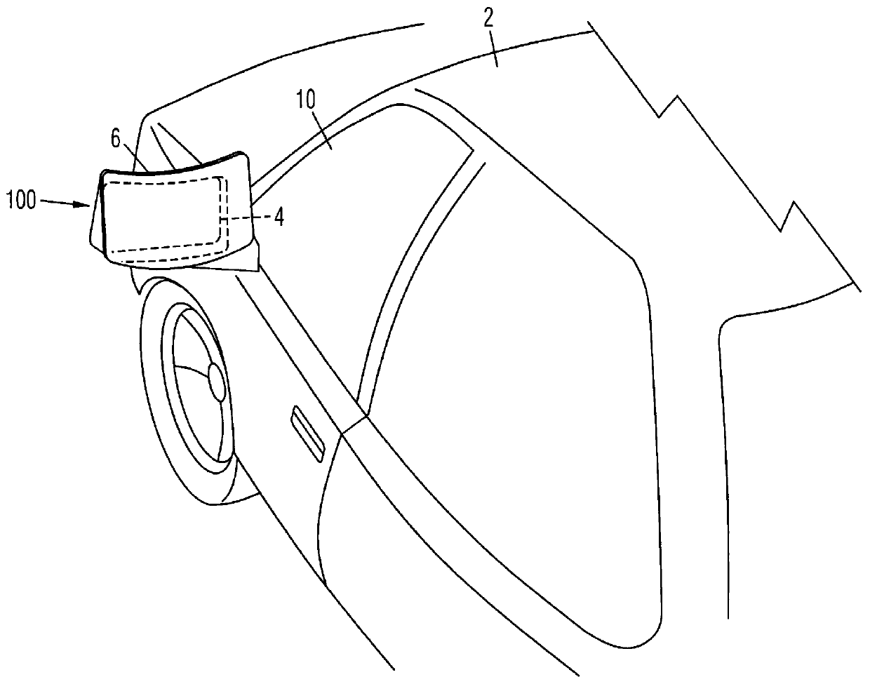
Referring now to FIG. 1 we see the blind spot mirror device of the present invention 100 in its attached mode to a standard driver's side rear view mirror 4 as found on most motor vehicles, in this case, an automobile 2. Note that the mirror 6 is outwardly curved. This configuration allows a driver to see a wider field of view than a conventional flat rear view mirror. Blind spot mirrors that are meant to be added onto the front surface of an existing rear view mirror are in the market place today however they are spherically convex in sha...


PUM


Abstract

A vehicle blind spot mirror with a mirror having a single plane outwardly curved surface, an extension member attached to the rear portion of the outwardly curved mirror and having a double stick foam tape attachment means on the opposite surface of the extension, allowing the extension and attached blind spot mirror to be affixed to a vehicle's existing rear view mirror even if the rear view mirror is set in a recessed frame, thereby allowing for a larger blind spot mirror than the original rear view mirror. A preferred embodiment includes wherein said outwardly curved mirror is approximately seven and one half inches wide and five inches tall and is radially curved in such a way that the vertical center axis of said mirror is raised between thirty and eighty thousandths of an inch higher than the right or left edge. An alternate embodiment wherein the outwardly curved mirror is installed in place of a traditional flat plane driver's side rear view mirror found in current motor vehicles.

Description

BACKGROUND OF THE INVENTIONThis invention relates generally to the field of rear view mirrors for motor vehicles, and more particularly to a vehicle blind spot mirror.Very soon after the invention of the motorized vehicle the need was identified for a means for a driver to see if other objects were in the rearward vicinity of the driver's vehicle. To this end rear view mirrors have been installed both inside the vehicle and outside the vehicle. Currently most automobiles have external rear view mirrors located at the bottom forward corner of the side window of the vehicle.A common problem that drivers experience when looking at the driver side rear view mirror is that there is a space which extends roughly between the rear of the driver's car and the driver's door where the rear view mirror does not pick up another vehicle or object completely. This location is commonly known as the blind spot. A number of products are available in the marketplace that attempt to solve the problem o...

Claims


Application Information

Patent Timeline
Patent Type & Authority Patents(United States)
IPC IPC(8): B60R1/08
CPCB60R1/082
Inventor GERDES, HARTMUT H.
Owner GERDES HARTMUT H
Why Eureka
Try Eureka