

Image display apparatus
a technology of image display and apparatus, which is applied in the field of image display apparatus, can solve the problems of unable to achieve the brightness of the display apparatus, the above-mentioned techniques, and the apparatus to be enlarged
- Summary
- Abstract
- Description
- Claims
- Application Information
AI Technical Summary
Problems solved by technology
Method used
Image

Examples
embodiment 2
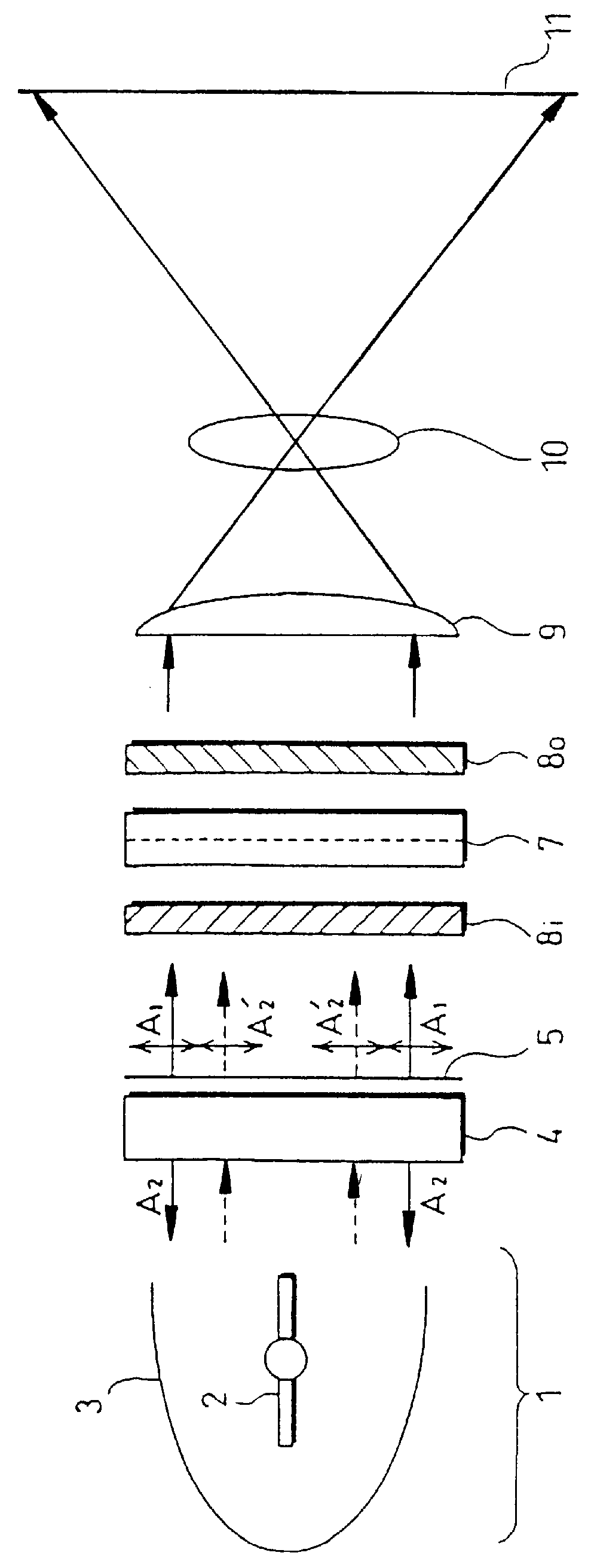
Referring to FIG. 5, a projection-type image display apparatus in another embodiment of the present invention will be described. FIG. 5 is a schematic view showing the projection-type image display apparatus. In FIG. 5, the components identical with those in Embodiment 1 are denoted by the reference numerals identical therewith, and the detailed description of these will be omitted.
The projection-type image display apparatus includes an illumination unit having a lamp 2 and a parabolic mirror (concave mirror) 3, a polarization selecting and reflecting element 6 (e.g., a retroreflecting sheet polarizer), a reflection-type liquid crystal display panel 7' displaying an image by modulating a polarization state of linearly polarized light based on an applied voltage to control transmittance, a polarization beam splitter 12, a polarizing plate 8.sub.o provided on a light beam output side of the polarization beam splitter 12, a projection element having a field lens 9 and a projection lens...
PUM
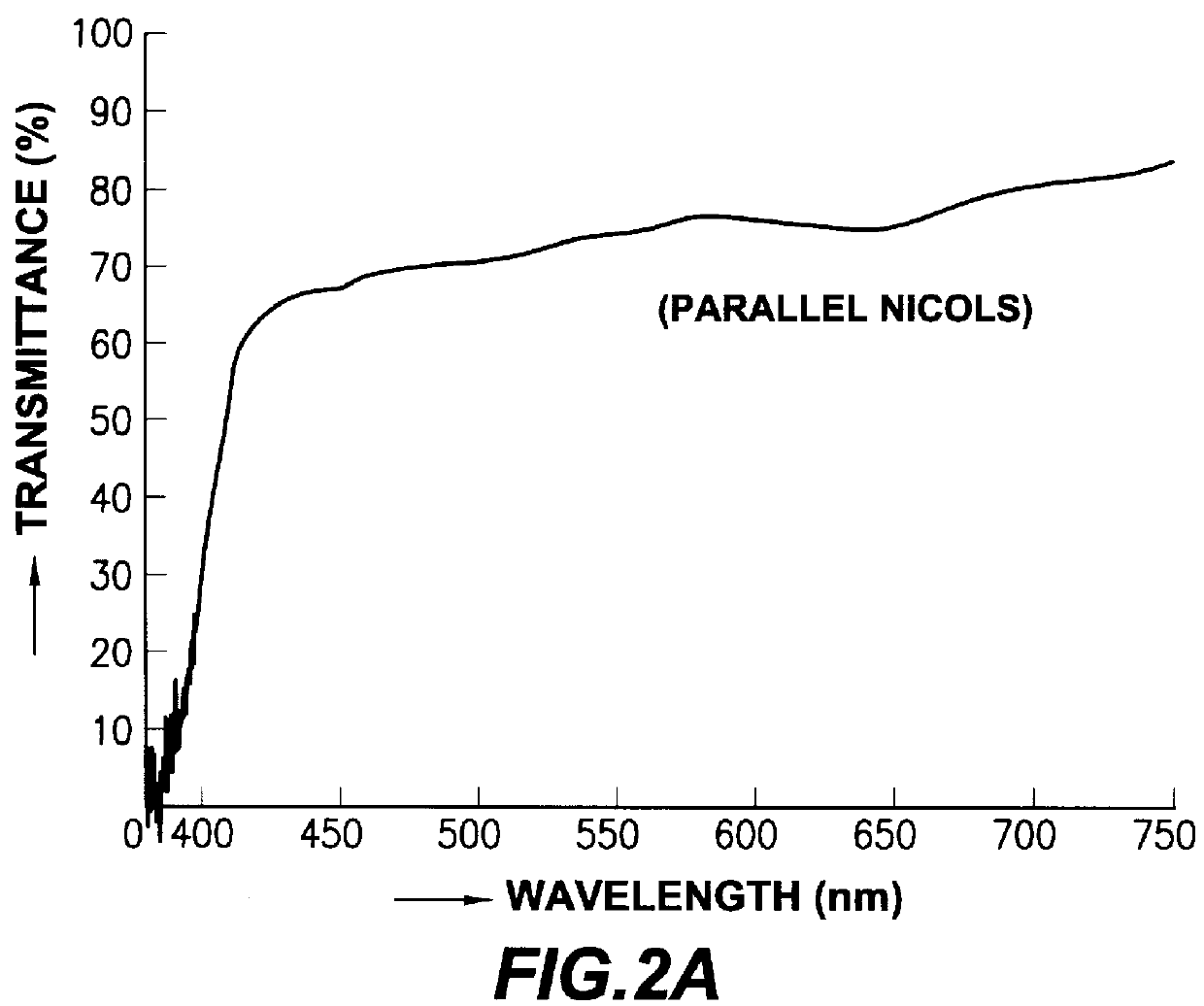
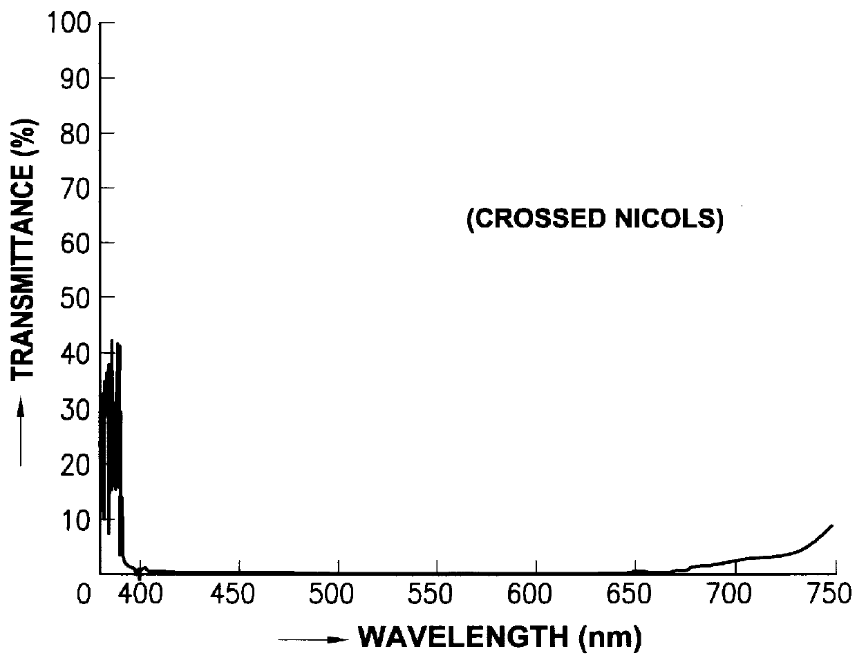
| Property | Measurement | Unit |
|---|---|---|
| transmittance | aaaaa | aaaaa |
| transmittance | aaaaa | aaaaa |
| transmittance | aaaaa | aaaaa |
Abstract
Description
Claims
Application Information