Self-watering planter employing capillary action water transport mechanism

a planter and water transport technology, applied in the field of self-watering planters, can solve the problems of affecting the service personnel, affecting the quality of plant watering, and affecting the quality of plant watering, and achieve the effect of reducing the cost of watering and other maintenance of plants, reducing the cost of watering and other maintenance, and reducing the cost of planter maintenan

Inactive Publication Date: 2000-06-27
COLOVIC ALEX J
View PDF60 Cites 67 Cited by
  • Summary
  • Abstract
  • Description
  • Claims
  • Application Information

AI Technical Summary

Problems solved by technology

A long-standing problem, however, arises from the need to properly water the plants.
This places a considerable burden on the service personnel which must ensure that each plant is properly watered.
As such, costs associated with watering and otherwise maintaining the plants can be substantial, particularly for large office complexes, shopping malls, and the like.
A first problem associated with self-watering planters of this type is that the integrated self-watering planter can be considerably more expensive than conventional planters.
Also, unless the manufacturer provides a set of self-watering planters of many different sizes, shapes and the like, the customer is limited in the choice of plant sizes thereby limiting the desirability of the self-watering planters.
Indeed, it may be difficult to find the appropriate container size and shape for particular plants to satisfy the needs of the customer.
The cost associated with providing integrated self-watering planters to accommodate such unique requirements may be prohibitive.
Yet another problem associated with integrated self-watering planters arises if the planter needs to be removed from its outer enclosure, perhaps to identify or correct a mechanical failure in the planter or perhaps because some form of plant failure has occurred and the plant itself needs to be replaced.
With the planter and the water reservoir integrally formed, the entire assembly may be extremely heavy and awkward to remove from its outer enclosure, particularly if the reservoir is still substantially filled with water.
Accordingly, considerable time and effort may be required by plant service personnel to remove the pl

Method used


Image

  • Self-watering planter employing capillary action water transport mechanism
  • Self-watering planter employing capillary action water transport mechanism
  • Self-watering planter employing capillary action water transport mechanism

Examples


Embodiment Construction

Various exemplary embodiments of the invention will now be described with reference to the figures. These embodiments merely illustrate various aspects of the invention and should not be construed as limiting the scope of the invention.

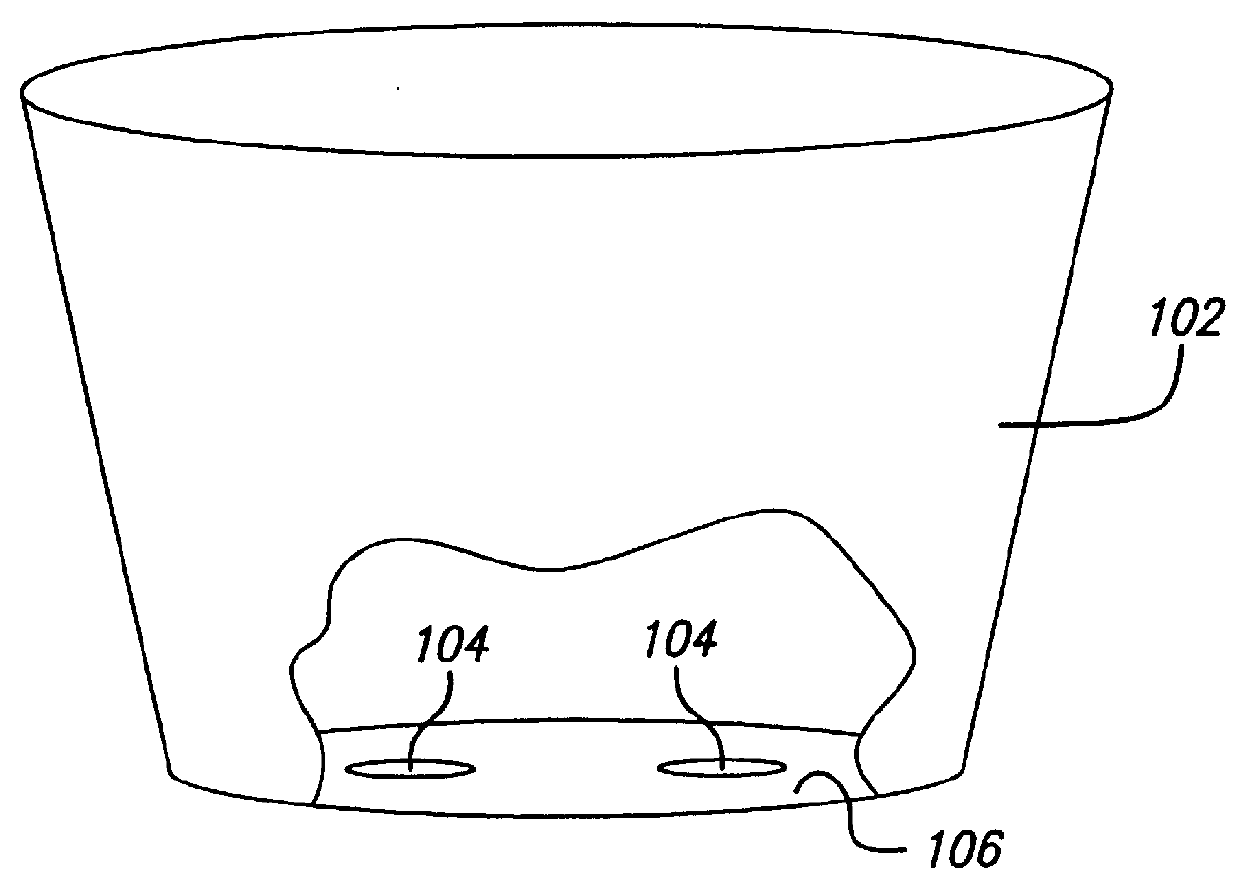
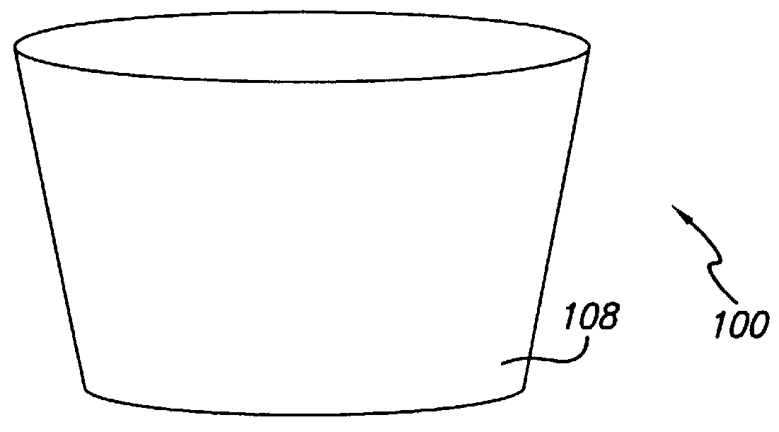
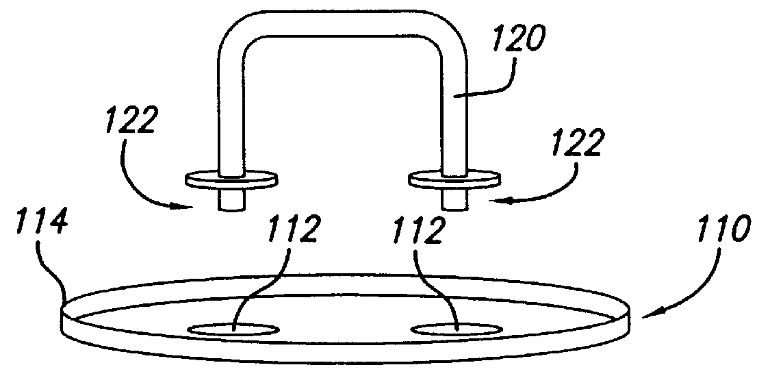
FIGS. 1-2 illustrate a self-watering assembly 100 for use in watering a plant (not shown) contained within a conventional planter 102 having circular flow hole apertures 104 formed within a base 106 of the planter. The self-watering assembly uses capillary action to withdraw water from a water reservoir 108 having a lid 110 with a set of apertures 112 formed within the lid. The lid additionally includes a rim 114 formed around a perimeter thereof.

Self-watering assembly 100 includes a set of water-permeable flow hole inserts 116 each including a portion of capillary material 118 which protrudes slightly from a base of the insert 116. Flow hole inserts 116 are generally conical as shown and are, in use, inserted into the circular flow hole 104 of the pl...


PUM


Abstract

The self-watering assembly is used in combination with a conventional planter having flow hole apertures formed within a base thereof. The assembly includes a set of water-permeable flow hole inserts each including a portion of capillary material such as spandex. The flow hole inserts are inserted into a flow hole of the planter for direct contact with soil positioned therein. The flow hole inserts are sized and shaped to securely fit within the flow hole preventing soil from falling out of the flow hole and preventing roots from growing through the flow hole. Additional capillary material, also formed of spandex, couples an interior of a water reservoir to the capillary material of the water-permeable inserts. By using spandex as the capillary material, sufficient capillary flow may be achieved to properly water even medium to large sized plants. By employing water-permeable inserts for insertion into the planter wherein the inserts have capillary material mounted therein, water can be more effectively drawn into the soil of the planter as compared to many self watering planters wherein the planter merely rests on capillary material. Also, upon removal of the planter from the water reservoir, the inserts typically remain mounted within the flow holes of the planter such that soil from the planter is prevented from falling out of the planter via the flow holes. Entirely conventional planters may be employed thereby reducing overall costs which permit the customer a wide choice of planter shapes and sizes.

Description

1. Field of the InventionThe invention relates to self watering planters.2. Description of the Related ArtLive plants are commonly provided in homes, offices and the like to provide a more aesthetically pleasing environment and also to help naturally filter the air. A long-standing problem, however, arises from the need to properly water the plants. Traditionally, each plant is individually watered as needed by pouring water directly into the soil of the planter containing the plant. In offices, retail establishments, and the like, professional water service personnel are often employed to water and otherwise maintain the plants. The frequency with which the plants need to be watered depends greatly however upon the type of plant, the ambient temperature, and the amount of light in the vicinity of the plant. As a result of these and other factors, some plants need to be watered once per day, others once per week, others perhaps less frequently. This places a considerable burden on t...

Claims


Application Information

Patent Timeline
IPC IPC(8): A01G27/04A01G27/00
CPCA01G27/04
Inventor COLOVIC, ALEX J.
Owner COLOVIC ALEX J
Why Eureka
Try Eureka